Crash analysis through estimation of residual strains resulting from metal formation

a residual strain and metal technology, applied in the field of crash analysis, can solve the problems of many types of mechanical components which form mechanical components of vehicles and other apparatuses may be subject to rupture failure, many types of mechanical components are subject to fatigue failure, and it is impossible to employ testing methods for real components, so as to increase the speed of the design process

Inactive Publication Date: 2007-11-01
BROWN CORP OF AMERICA INC
View PDF19 Cites 7 Cited by
  • Summary
  • Abstract
  • Description
  • Claims
  • Application Information

AI Technical Summary

Benefits of technology

[0029] In accordance with the invention, a method is provided for estimation and prediction of strains resulting from metal forming processes. The method is advantageous in that it can be used to estimate residual strains, without requiring the execution of forming simulations. A first-order crash a

Problems solved by technology

As an example, many types of materials which form mechanical components of vehicles and other apparatus may be subject to rupture failures due to fatigue.
In this regard, it is known that many types of mechanical components are subject to fatigue failures as a result of repeated loading and unloading.
As apparent, it is impossible to employ testing methods for testing of real components, since components are often destroyed during testing.
Although this technique may be characterized as correctly identifying a link between the phenomenon of a fatigue limit and the energy dissipation of material, it fails to present an operative method or apparatus for evaluating fatigue limits for real materials.
However, in standard polycrystalline materials, the complex response of the material under tensile stress will actually mask the point of inflection.
A problem associated with this method is that an arbitrary fixed criterion for identifying deterioration is employed, without taking into consideration specific properties of materials involved.
Also, the method fails to provide any quantitative information relating to a fatigue limit of the tested material.
In addition, the use of bending vibrations preclude the application of the method to components of relatively complex shapes.
Still further, the method includes steps of applying the component under test to environmental conditions, likely to effect the fati

Method used


Image

  • Crash analysis through estimation of residual strains resulting from metal formation
  • Crash analysis through estimation of residual strains resulting from metal formation
  • Crash analysis through estimation of residual strains resulting from metal formation

Examples


Embodiment Construction

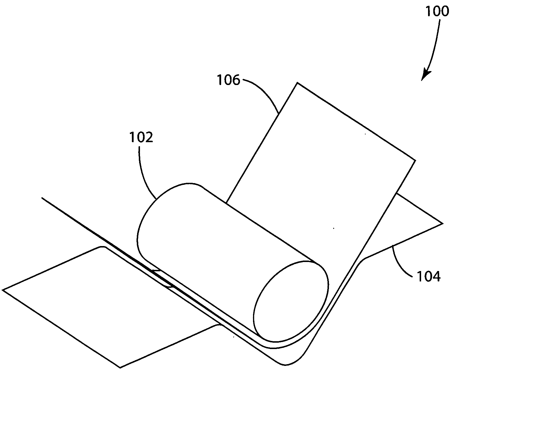
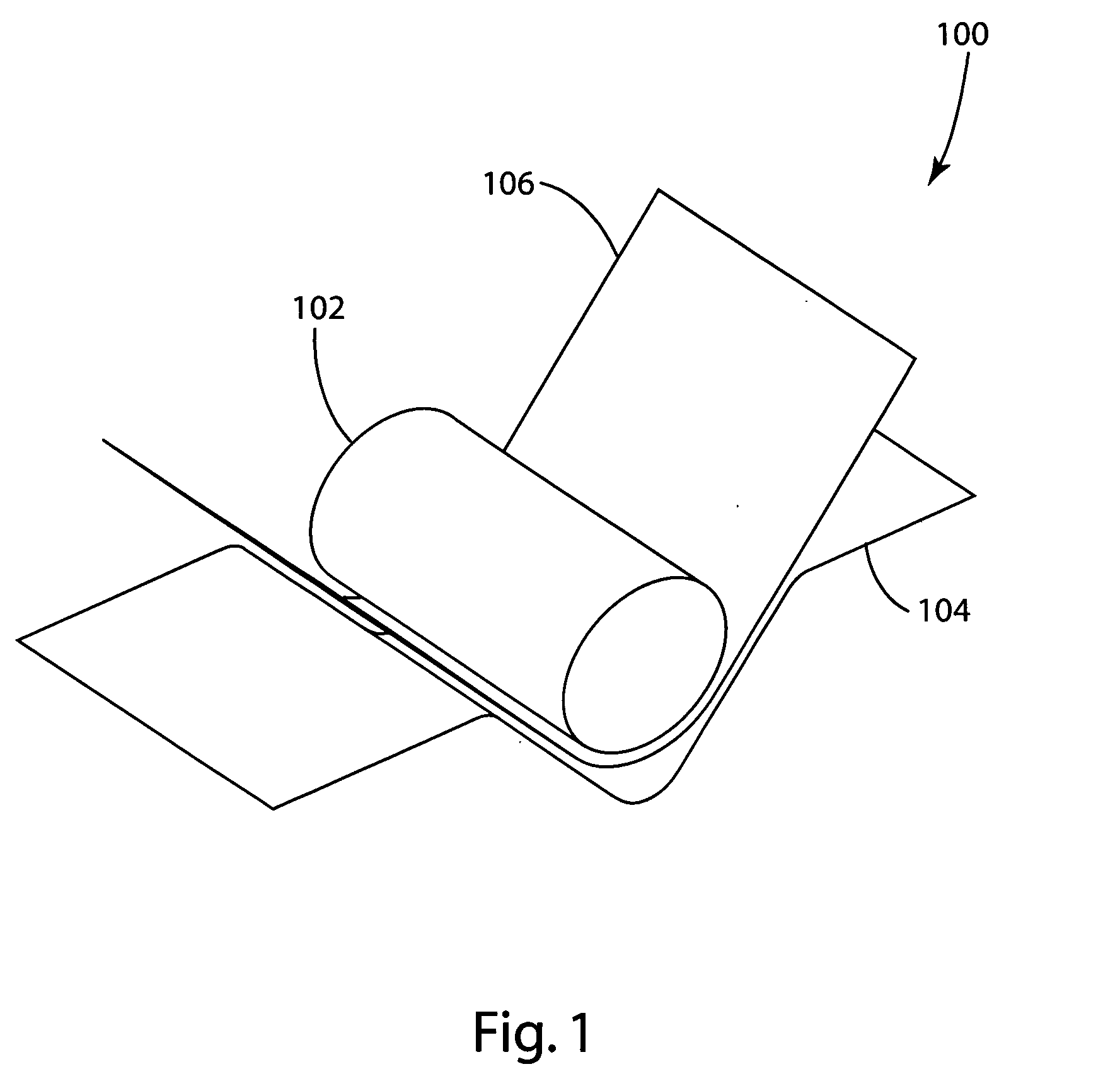
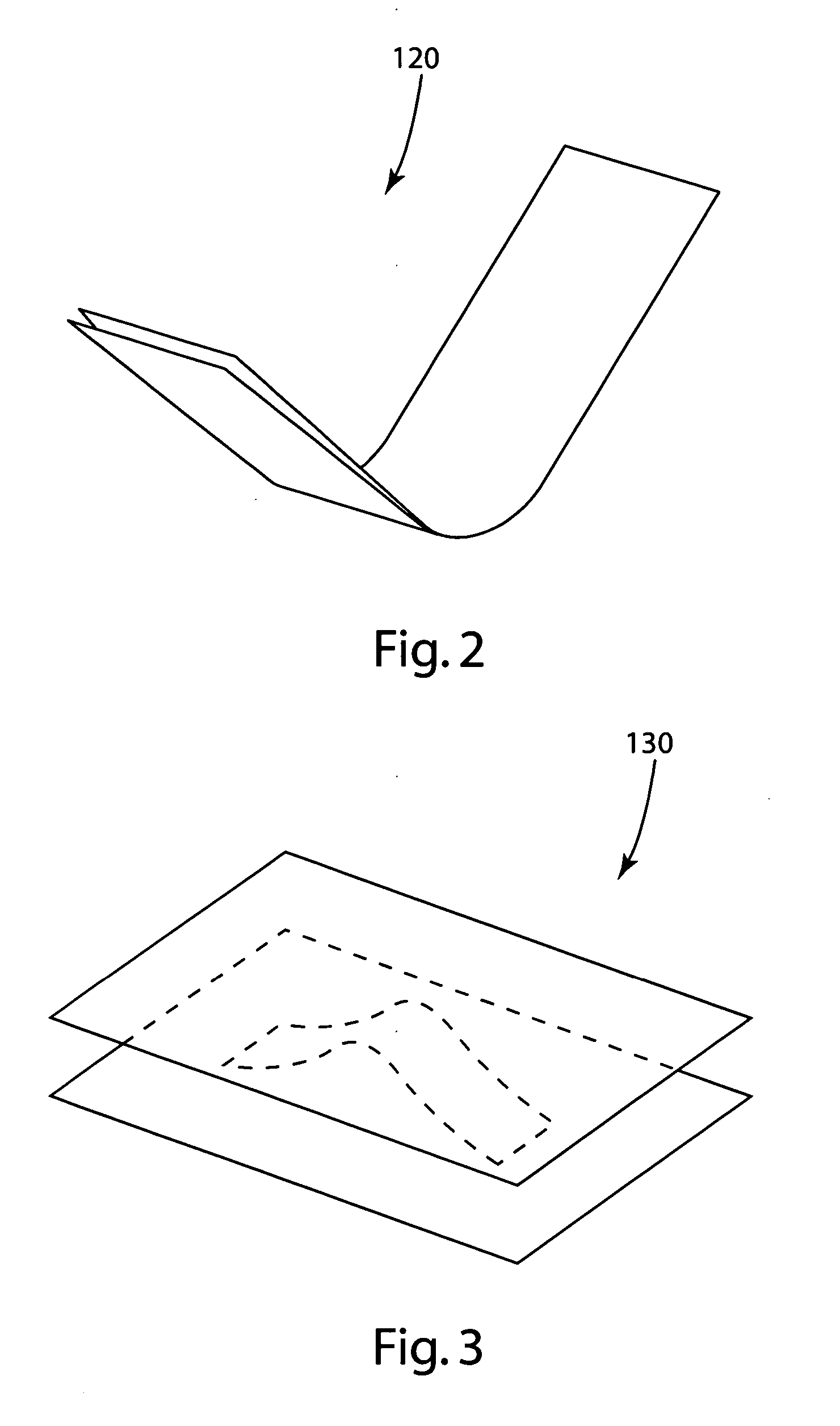
[0066] The principles of the invention are disclosed, by way of example, in a physically realized method for estimation of residual strains resulting from the forming of sheet metal. This method is described with respect to the illustrations and photographs set forth in FIGS. 1-28. As part of the description of an illustrative embodiment of the invention, results of use of the method in accordance with the invention are compared with determination of residual strains resulting from execution of metal forming simulations. As apparent from the subsequent description herein, and as applied to a first-order crash analysis, the use of estimated residual strains, rather than strains reported from several forming simulations, may increase the speed of the design process. As also set forth in subsequent paragraphs herein, test results are shown which were a physical realization of a comparison of a specimen part as formed, and an identical part which was heat treated for purposes of relievi...


PUM


Abstract

A method is disclosed for estimating or predicting residual strains resulting from metal formation. The method includes determining parameters indicative of physical and spatial characteristics of elements representing a formed metal part. A maximum plastic strain resulting from the metal forming processes is then estimated, as a function of the physical and spatial characteristics of a first one of the elements and a subset of the elements.

Description

CROSS-REFERENCE TO RELATED APPLICATIONS [0001] Not applicable. STATEMENT REGARDING FEDERALLY SPONSORED RESEARCH OR DEVELOPMENT [0002] Not applicable. REFERENCE TO A MICROFISHE APPENDIX [0003] Not applicable. BACKGROUND OF THE INVENTION [0004] 1. Field of the Invention [0005] The invention relates to crash analysis and, more particularly, methods for estimating or predicting residual strains resulting from metal formation. [0006] 2. Background Art [0007] For a substantial period of time, scientists and engineers have been interested in the causes of crashes, including those associated with automobiles, trains, airplanes and other vehicles and moving apparatus. Many of these studies in crash analysis are directed to human factors, including both physical and psychological considerations. Analysis of such factors as being impactive on airplane crashes have resulted in substantial modifications and redesigns over the years regarding pilot instrumentation panels. These redesigns have low...

Claims


Application Information

Patent Timeline
IPC IPC(8): G01B7/16
CPCG01N3/32G01N2203/0216G01N2203/0214G01N2203/0069
Inventor BROENE, WILLIAM JOHN
Owner BROWN CORP OF AMERICA INC
Why Eureka
Try Eureka