Tandem organic electroluminescent device

an electroluminescent device and organic technology, applied in the direction of discharge tube luminescnet screens, discharge tube/lamp details, electric discharge lamps, etc., can solve the problems of poor reproduction, thin electrodes, and the electrode patterning process employing shadow masks is not suitable for large display fabrication, etc., to achieve the effect of not increasing the complexity of the process

Active Publication Date: 2007-11-01
AU OPTRONICS CORP
View PDF7 Cites 25 Cited by
  • Summary
  • Abstract
  • Description
  • Claims
  • Application Information

AI Technical Summary

Benefits of technology

[0017]Accordingly, an object of the invention is to provide a novel tandem organic electroluminescent device, solving the aforementioned problems, without increased process complexity.

Problems solved by technology

However, the electrode is thin enough that reproductively thereof is poor.
The electrode patterning process employing shadow mask is not suitable for use in large display fabrication.
Since the tandem type organic electroluminescent device utilizes high operating voltage, the carrier transport ability of the connection layer is weakened due to carrier diffusion effect.
Suitable material of the charge generating layer, however, is currently unavailable and usually toxic (such as V2O5).
Therefore, it is difficult to achieve mass production.
Moreover, the charge generating layer comprising V2O5 has high resistance, resulting in a high driving voltage of the tandem type organic electroluminescent device.

Method used


Image

  • Tandem organic electroluminescent device
  • Tandem organic electroluminescent device
  • Tandem organic electroluminescent device

Examples


Embodiment Construction

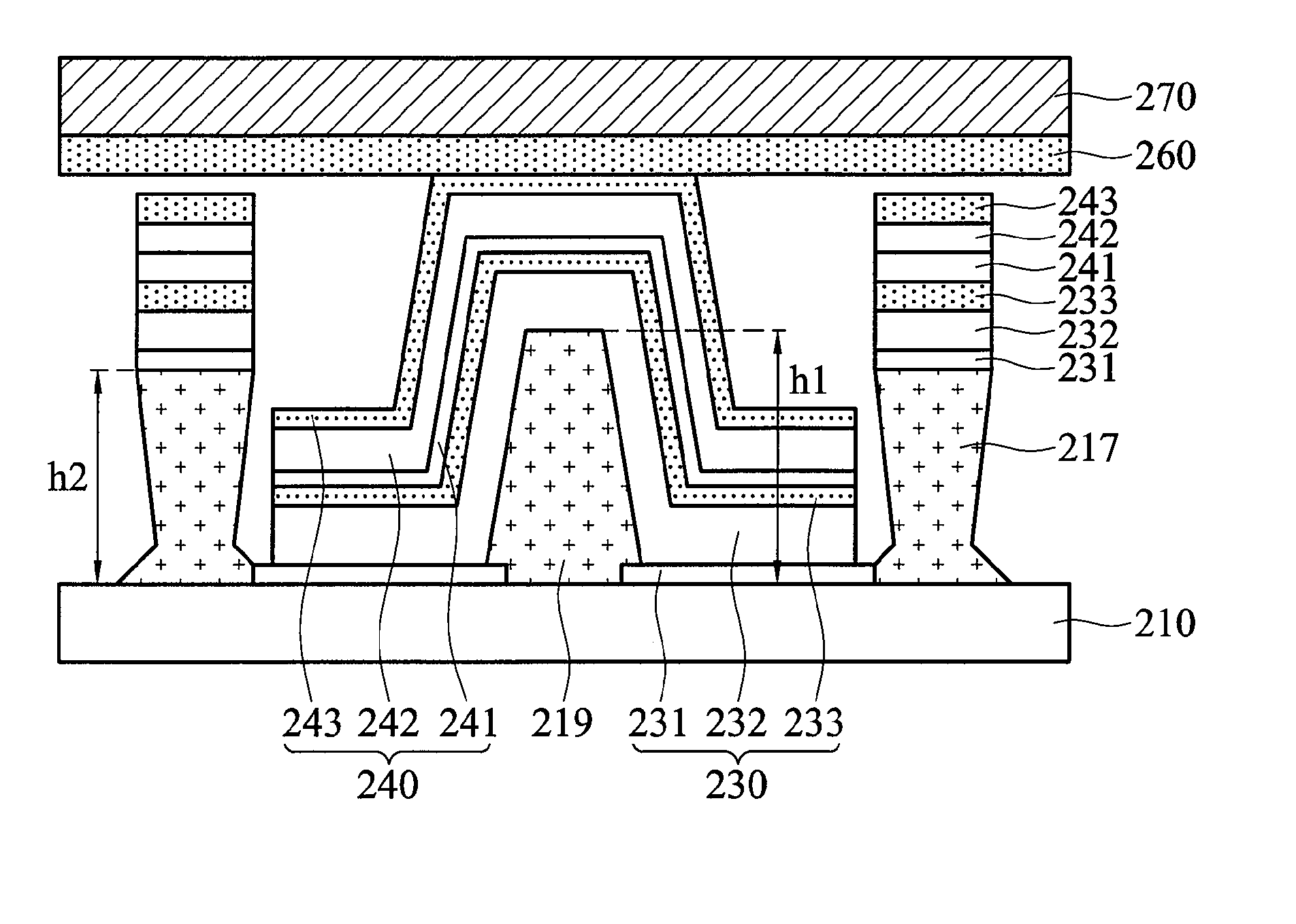
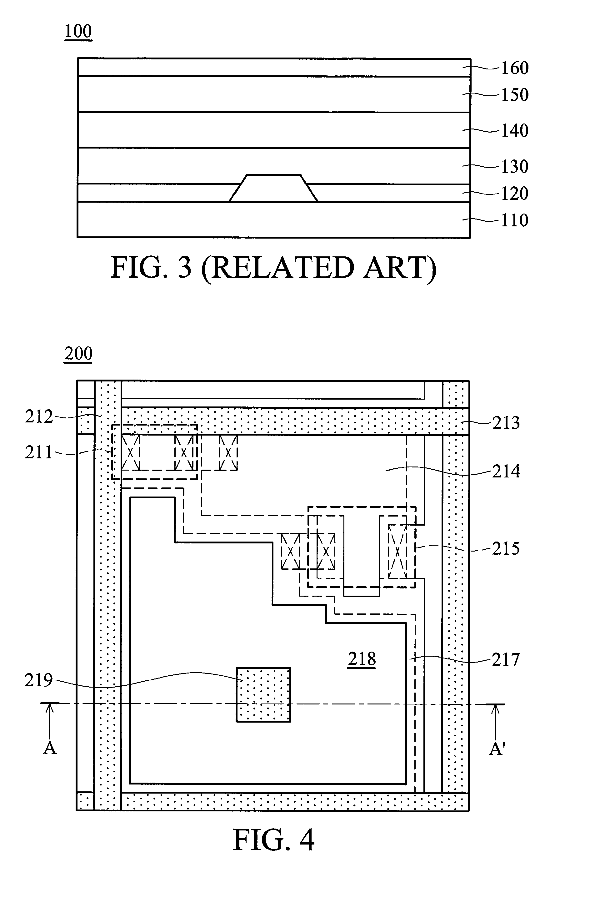
[0031]FIG. 4 is a partial schematic diagram of a tandem organic electroluminescent device according to an embodiment of the invention. The tandem organic electroluminescent device comprises a plurality of pixel areas 200 arranged in a matrix.

[0032]Each pixel area 200 comprises a thin film transistor 211 electrically connected to a data line 212 extending along a Y axis, a scan line 213 extending along an X axis, a capacitor 214, a pixel thin film transistor 215, and a rib 217 with chambered corners. The rib 217 with chambered corners is formed on the substrate, surrounding a display region 218. Particularly, the pixel area 200 further comprises a protrusion 219 formed within the display region 218. Further, the pixel area 200 further comprising a plurality of organic light emitting diodes stacked vertically in the display region 218, covering the protrusion 219. Each organic light emitting diode comprises a bottom electrode, an organic electroluminescent layer, and a top electrode (...


PUM


Abstract

A tandem organic electroluminescent device. The tandem organic electroluminescent device comprises a substrate having a pixel thin film transistor. A rib with chambered corners is formed on the substrate, surrounding a display region. A protrusion is formed in the display region. A plurality of organic light emitting diodes is stacked vertically in the display region, covering the protrusion, wherein each organic light emitting diode comprises a top electrode, an organic electroluminescent layer, and a bottom electrode. The bottom electrode of the bottommost organic light emitting diode is electrically connected to the pixel thin film transistor. A common electrode electrically connected to the top electrode of the topmost organic light emitting diode directly over the protrusion.

Description

BACKGROUND OF THE INVENTION[0001]1. Field of the Invention[0002]The invention relates to an organic electroluminescent device, and more particularly to a tandem organic electroluminescent device.[0003]2. Description of the Related Art[0004]Recently, with the development and wide application of electronic products, such as mobile phones, PDA, and notebook computers, there has been increasing demand for flat display elements which consume less electric power and occupy less space. Among flat panel displays, organic electroluminescent devices are self-emitting, and highly luminous, with wider viewing angle, faster response, and a simple fabrication process, making them the industry display of choice.[0005]An organic light-emitting diode (OLED) is a light-emitting diode that uses an organic layer as the active layer. In recent years, OLEDs have been gradually employed in flat panel displays. The trend in organic electroluminescent display technology is for higher luminescent efficiency ...

Claims


Application Information

Patent Timeline
Patent Type & Authority Applications(United States)
IPC IPC(8): H05B33/00H01L51/50
CPCH01L27/3246H01L27/3209H10K59/32H10K59/122
Inventor LEE, HSIN-HUNGLEE, CHUNG-CHUN
Owner AU OPTRONICS CORP
Why Eureka
Try Eureka