Methods and Apparatus for Electroerosion

a technology of electroerosion and electromachining, applied in the field of electroerosion, can solve the problems of wasting time and money on workpieces, increasing the cost of blisks, and scrapping them with the attendant loss of time and expens

Inactive Publication Date: 2007-11-08
GENERAL ELECTRIC CO
View PDF46 Cites 37 Cited by
  • Summary
  • Abstract
  • Description
  • Claims
  • Application Information

AI Technical Summary

Problems solved by technology

Since the blisk workpiece requires multiple stages of manufacture and machining immediately prior to the forming of the airfoils therein considerable time and money are invested in the workpiece.
And, as each of the multitude of airfoils around the blisk perimeter is machined, additional time and expense are invested which further increases the cost of the blisk.
Unacceptable damage to any one of the blisk airfoils or the supporting rotor disk itself during the various stages of manufacturing could render the entire blisk unusable for its intended use in a high performance gas turbine engine resulting in scrapping thereof with the attendant loss of time and expense.

Method used


Image

  • Methods and Apparatus for Electroerosion
  • Methods and Apparatus for Electroerosion
  • Methods and Apparatus for Electroerosion

Examples


example 1

[0077]

TABLE 1PercentageConstituentFunction(wt %)TriethanolamineAnti-rusting8Sodium MolybdateAnti-rusting8Potassium oleateAnti-rusting6Potassium carbonateIncreasing conductivity6Silicone defoaming additiveDefoaming3Tri-Sodium CitrateLucent additive20Polyvinyl AlcoholBurst additive8Emulsifier OP-10Surface-active medium1Pure waterCarrier34Indurstry oil 20#Lubricant6

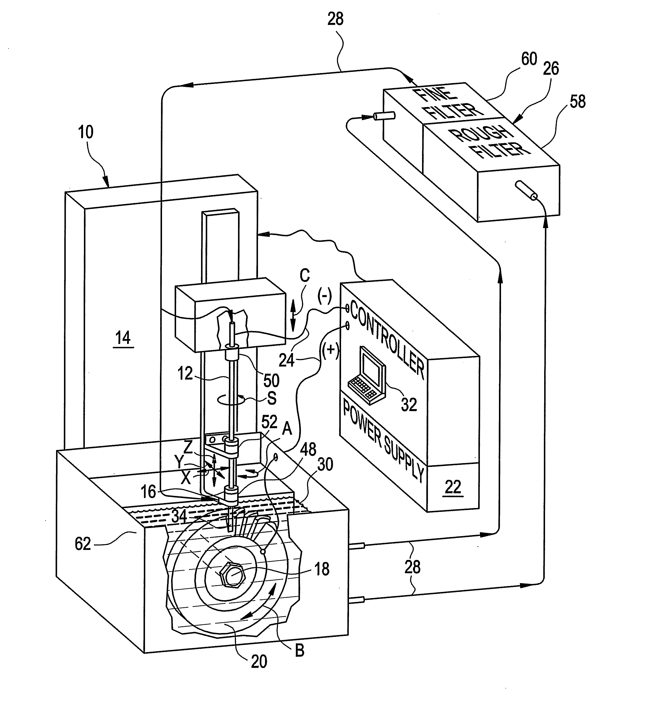
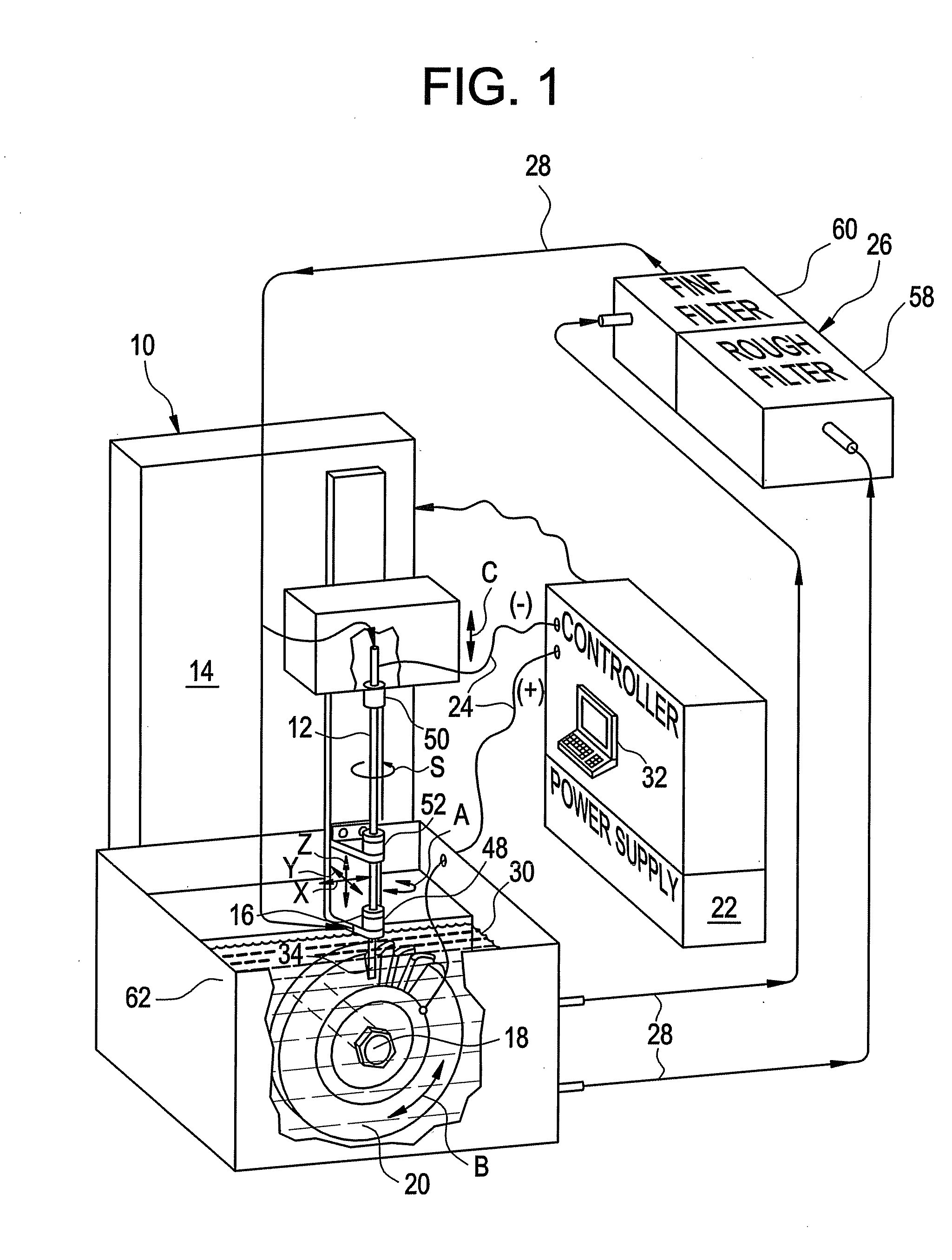
[0078] The constituents set forth in Table 1 were combined and mixed to form the electrolyte solution. The electrolyte was used in an electroerosion system such as that set forth in FIG. 3. A blisk of Inconel 718 (i.e., a high temperature nickel based alloy blisk) was processed using the developed electrolyte at a removal rate of 4,000 mm3 / min at a current of 280 amps. The results show the advantages of the developed electrolyte formulation, namely, (i) improvement of the machined surface without the stuck particle (i.e., during the machining, no particles stick to the machined surface); (ii) a stable machining process witho...

example 2

[0079]

TABLE 2PercentageComponentsFunction(wt %)TriethanolamineAnti-rusting7Sodium MolybdateAnti-rusting, electrolyte7Tri-Sodium CitrateLucent additive, electrolyte15Polyvinyl AlcoholBurst additive15Emulsifier OP-10Surface-active medium2Indurstry oil 20#Lubricant5Potassium oleateIncreasing conductivity10Silicone defoaming agentDefoaming1Pure waterCarrier38

[0080] The introduction of distributed multiple electrical arcs between the spinning electrode and the workpiece in the presence of an electrolyte therebetween permits a substantial increase in the material removal rate of the electroerosion process which substantially exceeds the material removal rates of EDM and ECM processes. Where those latter processes intentionally prohibit electrical arcing between the electrode and workpiece, the distributed arc process disclosed above preferentially introduces multiple electrical arcs with high average current density (e.g., greater than or equal to about 5 amps / mm2) for maximizing material...


PUM

PropertyMeasurementUnit
diameteraaaaaaaaaa
sizeaaaaaaaaaa
diameteraaaaaaaaaa

Abstract

An electroerosion apparatus comprising: an electrode, a multiaxis machine, an electrolyte supply including a conduit for circulating an electrolyte, and a controller in operative communication with the multiaxis machine and configured for distributing intermittent multiple electrical arcs between the electrode and a workpiece. The multiaxis machine comprises a tool head configured to support and to spin the electrode, and a spindle configured to support a workpiece. The electrolyte comprises an anti-rusting agent, a defoaming agent, a lucent additive, a burst additive, a surface active medium, a lubricant, and water, and has a conductivity of about 0.1 milliSiemens to about 30 milliSiemens. In one embodiment, the method of electroerosion machining a workpiece comprises: creating relative motion between a spinning electrode and a workpiece; circulating an electrolyte around the spinning electrode, and distributing multiple electrical arcs between the electrode tip and the workpiece.

Description

CROSS-REFERENCE TO RELATED APPLICATION [0001] The present application is a continuation-in-part of U.S. patent application Ser. No. 10 / 842,344 filed May 7, 2004, and incorporated herein in its entirety.BACKGROUND [0002] This application relates generally to electromachining, and more particularly, to an electrolyte solution for electromachining. [0003] Precision machining is commonly effected using multiaxis numerically controlled (NC) milling machines. The cutting tool is suspended from a tool head that typically has three orthogonal axes of translation and one or more additional axes of rotation corresponding therewith. The workpiece or part to be machined is fixedly mounted to a bed which may impart additional axes of translation or rotary movement thereto. [0004] During operation, the NC machine is programmed in software for controlling the machining or cutting path of the tool for precisely removing material from the workpiece to achieve the desired final dimensions thereof. Th...

Claims


Application Information

Patent Timeline
Patent Type & Authority Applications(United States)
IPC IPC(8): B23H3/00B23H1/02B23H1/00B23H7/26B23H7/32B23H9/10B23K9/013
CPCB23H1/022B23H7/32B23K9/013B23H2400/10B23H9/10B23H5/02
Inventor WEI, BINLAMPHERE, MICHAELHAYASHI, STEVENWESSELS, JEFFREYYUAN, RENWEILUO, YUANFENGZHAN, YIMIN
Owner GENERAL ELECTRIC CO
Why Eureka
Try Eureka