Carbon Nanotube Structure-Selective Separation and Surface Fixation

a carbon nanotube and structure technology, applied in fuel cells, water/sewage treatment by substance addition, water/sewage treatment by irradiation, etc., can solve the problem that the separation method among the existing production methods cannot allow a selective synthesis of a single-walled carbon nanotube which has a particular diameter, and the absolute potential information is limited, so as to achieve high selective separation

Inactive Publication Date: 2007-11-08
JAPAN SCI & TECH CORP
View PDF5 Cites 65 Cited by
  • Summary
  • Abstract
  • Description
  • Claims
  • Application Information

AI Technical Summary

Benefits of technology

[0078] The present method and/or apparatus described herein can provide highly selective separation, concentration or purification of carbon nanotubes having a u

Problems solved by technology

However, any method among the existing production methods does not allow a selective synthesis of a single-walled carbon nanotube which has a particular diameter.
Therefore, to date, the length-based separations of carbon nanotubes is not sufficient to define the characteristic physical property thereof.
However, all of these Patent Documents 1 to 5 only disclose techniques of impurity removal.
Although various studies have contributed to the char

Method used


Image

  • Carbon Nanotube Structure-Selective Separation and Surface Fixation
  • Carbon Nanotube Structure-Selective Separation and Surface Fixation
  • Carbon Nanotube Structure-Selective Separation and Surface Fixation

Examples


example 1

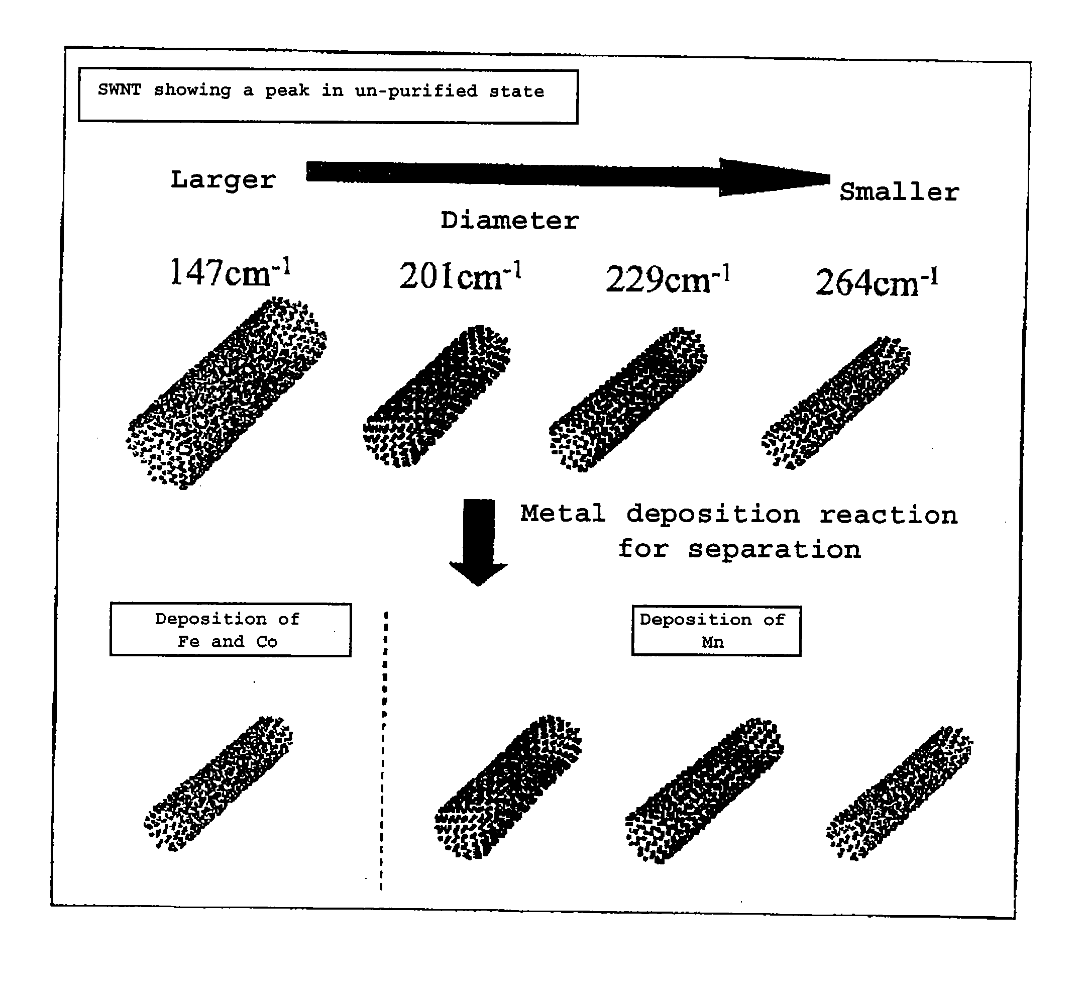
1.1 Metal Deposition on a Carbon Nanotube

[0192] Carbon nanotubes (CarboLex AP-Grade SWNT (SWNT: purity 50-70%)) in an aqueous 1% sodium dodecyl sulfate (SDS) solution were subjected to ultrasonic dispersion treatment at 24° C. and 12000 rpm for 15 minutes and the supernatant solution was filtered with a syringe filter (0.2 μm pore size filter) and subjected to additional ultrasonic treatment and centrifugal separation in the same conditions to obtain a micellar dispersion.

[0193] Next, methanol (Methanol: 99.8% purity, Infinity Pure Grade; commercially available from Wako Pure Chemical Industries, Ltd.) was added as an electron donor to the dispersion to a concentration of 0.1%. The following three different metal ion solutions were added to the above resulting solution to prepare three solutions with different metal ions.

[0194] I) 0.1 M Fe(NH4)2(SO4)2 aqueous solution

[0195] II) 0.1 M CoCl2 aqueous solution

[0196] III) 0.1 M MnCl2 aqueous solution

[0197] Monochromatic light with ...

example 2

[0201]FIG. 8 is an apparatus structural drawing showing one embodiment of the invention. Light with different wavelength values 1064 nm (λ1), 785 nm (λ2), and 514 nm (λ3) were employed as light irradiation sources for photoelectric chemical metal deposition. A micellar dispersion obtained by dispersing the carbon nanotube before purification in an aqueous 1% sodium dodecyl sulfate solution was used as the carbon nanotube-containing solution. A thin film glass was fixed in a reaction vessel and Fe(NH4)2(SO4)2 was added to the carbon nanotube-containing solution to a concentration of 0.1 M and light irradiation with the wavelength (λ1, λ2, or λ3) to the substrate was carried out for 10 minutes. After the carbon nanotube bearing the deposited metal was accumulated on the substrate, the carbon nanotube was washed with sulfuric acid and subjected to Raman spectroscopic measurement in the radial breathing mode to determine the chiral vector of the deposited carbon nanotube. In the portion...

example 3

[0202]FIG. 9 shows a drawing of an experiment carried out similar to that in the above-mentioned Example 2 with additional steps of flowing the carbon nanotube-containing solution and supplying the obtained carbon nanotube dispersion continuously. As a result, the carbon nanotube could be deposited selectively as similarly described above, resulting in a two to ten times increase in the amount of the deposition.


PUM

PropertyMeasurementUnit
Fractionaaaaaaaaaa
Fractionaaaaaaaaaa
Diameteraaaaaaaaaa

Abstract

A method of separating, concentrating or purifying uniform carbon nanotubes with desired properties (diameter, chiral vector, etc) in a highly sensitive manner by the use of structure-sensitive properties peculiar to carbon nanotubes; and an apparatus therefor. There is provided a method of separating, concentrating, or purifying carbon nanotubes with the desired properties contained in a sample, comprising the steps pf (a) irradiating a sample containing carbon nanotubes with light; and (b) selecting carbon nanotubes with desired properties. In a preferred embodiment, the light irradiation of the step (a) can be carried out in the presence of a metal so as to cause specified carbon nanotubes to selectively induce a photocatalytic reaction, resulting in metal deposition. Further, in a preferred embodiment, a given magnetic filed can be applied in the steps (b) so as to attain accumulation or concentration or carbon nanotubes with metal deposited.

Description

TECHNICAL FIELD [0001] The present invention relates to a method and an apparatus for highly selectively separating, concentrating, and refining carbon nanotubes (CNTs). The invention also relates to a high purity carbon nanotube separated by the method of the invention, and a thin film and an array thereof. The invention further provides an optical device or an electronic device using the carbon nanotube film. BACKGROUND ART [0002] A carbon nanotube is a new substance discovered by Sumio Iijima in 1991, which can exhibit a metallic and / or semiconducting property depending on the diameter thereof and the way the tube is wound. The individual physical property of the carbon nanotube is entirely different depending on the structure of the tube, and study within the art is currently being vigorously undertaken. In addition, the carbon nanotube is a substance, of which much is expected as a next generation material for use in devices and the like, having applications in the field of ele...

Claims


Application Information

Patent Timeline
IPC IPC(8): C01B31/02B82B3/00G01N13/14G01N27/00G01N30/88G01N37/00G01P15/00H01M4/88H01M4/96B01D39/20B82B1/00B82Y15/00B82Y30/00B82Y35/00B82Y40/00B82Y99/00G01P15/08H01M4/86
CPCB82Y15/00B82Y30/00B82Y40/00C01B31/0266C01B2202/02C01B2202/30Y02E60/50G01N2030/8859G01P15/08G01P15/0802H01M4/8605H01M4/9083H01M4/96C01B2202/36Y10S977/748Y10S977/848Y10S977/745Y10S977/845Y10S977/751C01B32/172C01B32/17
Inventor MURAKOSHI, KEI
Owner JAPAN SCI & TECH CORP
Why Eureka
Try Eureka