Control Method for a Robot

a robot and control method technology, applied in the field of robot control methods, can solve the problems of increasing friction, increasing load on the bearings, and difficult movement in response to external forces, and achieve the effects of reducing frictional forces, reducing frictional forces, and reducing frictional forces

Active Publication Date: 2007-11-08
ABB (SCHWEIZ) AG
View PDF6 Cites 80 Cited by
  • Summary
  • Abstract
  • Description
  • Claims
  • Application Information

AI Technical Summary

Benefits of technology

[0010] The principal advantage of the invention is that control over the robot while it is operated under compliance control is more exact. The force or forces required from a human operator to move or guide a robot arm in a certain direction is / are reduced in magnitude. The invention reduces the effect of friction, especially in bigger or heavier robots, by means of introducing oscillations (called “dithering” hereafter) in at least one of the motors and transmissions of the robot in a controlled manner, such that the level of oscillations is high enough to overcome static friction and stiction, but limited to avoid exciting vibrations of the robot end effector. The operator can also move the robot arm or tool more quickly between the desired points in space because the reduced effect of frictional forces during compliant control enable a faster, accurate response by the servo motors or actuators. It should be noted that the invention may be embodied as a manipulator arm rather than an industrial robot that that may have a plurality of rotational / translational axes.
[0011] Another advantage of the invention is that changeover from normal robot control to compliance control is accomplished in a better regulated manner, making it easier to begin teaching or configuring a robot, and also to switch back to normal operating control.
[0012] Another further advantage is that movement of the robot during maintenance service work or changes in production, is simplified and improved thus reducing down time and service time. This is very advantageous when using robots to tend other machines, for example to supply a workpiece to a welding robot for welding or to remove a component after an operation has been carried out by another machine, as set-up times and configuration or re-configuration times can be reduced. In addition, set-up times required during production changeovers to facilitate flexible manufacturing, or to suit changes in the specification of a product manufactured using traditional batch or continuous production may be greatly reduced.

Problems solved by technology

However with some robots having gearboxes that have high gear ratios, and for some larger robots with heavier parts, and also under conditions of varying temperature, there is a tendency of increased friction and variation in friction under operation that makes accurate movement in response to externally applied forces difficult.
Increased friction is also due in part to the use of pre-stressed bearings and pre-stressed gears which improve structural stiffness of the various components but cause increased loads on the bearings, and thus increased friction.
Another problem is that reaction forces can arise sometimes in a second axis in response to movements of a large amplitude in a first axis, which further complicates accurate control of the forces in one or more axes.

Method used


Image

  • Control Method for a Robot
  • Control Method for a Robot
  • Control Method for a Robot

Examples


Embodiment Construction

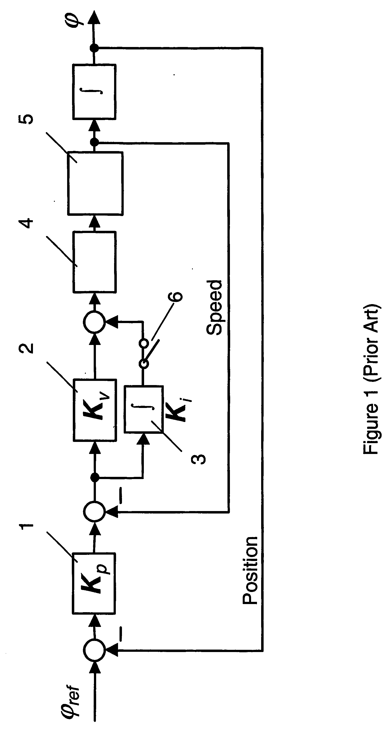
[0025]FIG. 1 (Prior Art) shows a control loop for controlling one axis of a robot, as it is normally used for control of robots. The control is a cascade control comprising an internal velocity control loop with PI-controllers 2, 3 and an external position control loop (with position measurement on the motor side) with P-controller 1. The parameters of the control are usually selected as high as possible in order to ensure that the robot follows the path generated according to a series of desired positions, as accurately as possible, and also under the influence of external forces. The motor torque control servo 4 providing an input with a torque reference is shown and a motor, gear / gearbox and arm indicated schematically as another block 5.

[0026] In the Prior Art control method in order to attain the desired compliance of the robot, in 1, 2 the integral component of the PI-controllers of the velocity control loop 3 is disconnected at switch 6 when changing from normal to complianc...


PUM


Abstract

An apparatus, a method and a control system for controlling an industrial robot with at least one axis of rotation and/or translation. The robot includes at least one actuator or motor at each of the axes for driving a movement of an arm of the robot and at least one sensor at each of the rotatable shafts. A dither-signal generator for generation of a periodic signal is used to provide a varying dither signal to a servo of the actuator. Automatic adaption of the dither signal is provided. A computer program for carrying out the method and a graphical user interface.

Description

TECHNICAL FIELD [0001] The invention relates to a robot control method and to an industrial robot or other automation machine regulated or controlled by said method. In particular, the method is concerned with controlling robot movement in at least one axis of rotation under an externally imposed force. BACKGROUND ART [0002] U.S. Pat. No. 4,670,641 entitled: Machine robot, particularly for welding; describes a robot arm for use with an industrial robot. The robot arm has a multiplicity of degrees of freedom. The various parts of the robot arm are rotatable about a plurality of axes. A servo-system for one of the degrees of freedom is capable of disengaging a part of its feedback network, whereby the adjustment passes from Proportional Integral (PI type) control to Proportional (P-type) control. This is done because the accuracy and precision of the robot arm control can surpass the precision of part of the workpiece being welded or otherwise processed. The fine adjustment of the ser...

Claims


Application Information

Patent Timeline
Patent Type & Authority Applications(United States)
IPC IPC(8): G05B15/00B25J9/16G05B13/02
CPCB25J9/1641G05B2219/41156G05B13/025
Inventor KOCK, SONKEMULLER, CHRISTIAN H.BROGARDH, TORGNYBERGSJO, JESPEROLEVIK, ANDREASMOBERG, STIG
Owner ABB (SCHWEIZ) AG
Why Eureka
Try Eureka