Fuel Injector with Punch-Formed Valve Seat for Reducing Armature Stroke Drift

a technology of armature stroke and injector, which is applied in the direction of liquid fuel feeder, machine/engine, mechanical apparatus, etc., can solve the problems of increasing the distance that the closing element must travel in order to close the outlet throttle, armature stroke drift, and wear on the valve sea

Inactive Publication Date: 2007-11-15
ROBERT BOSCH GMBH
View PDF7 Cites 9 Cited by
  • Summary
  • Abstract
  • Description
  • Claims
  • Application Information

AI Technical Summary

Problems solved by technology

This continuous switching of the closing element generates wear on the valve seat.
This wear results in armature stroke drift.
In other words, the distance that the closing element must travel in order to close the outlet throttle increases due to the wear.
This results in longer opening and closing time

Method used


Image

  • Fuel Injector with Punch-Formed Valve Seat for Reducing Armature Stroke Drift
  • Fuel Injector with Punch-Formed Valve Seat for Reducing Armature Stroke Drift
  • Fuel Injector with Punch-Formed Valve Seat for Reducing Armature Stroke Drift

Examples


embodiment

VARIANTS

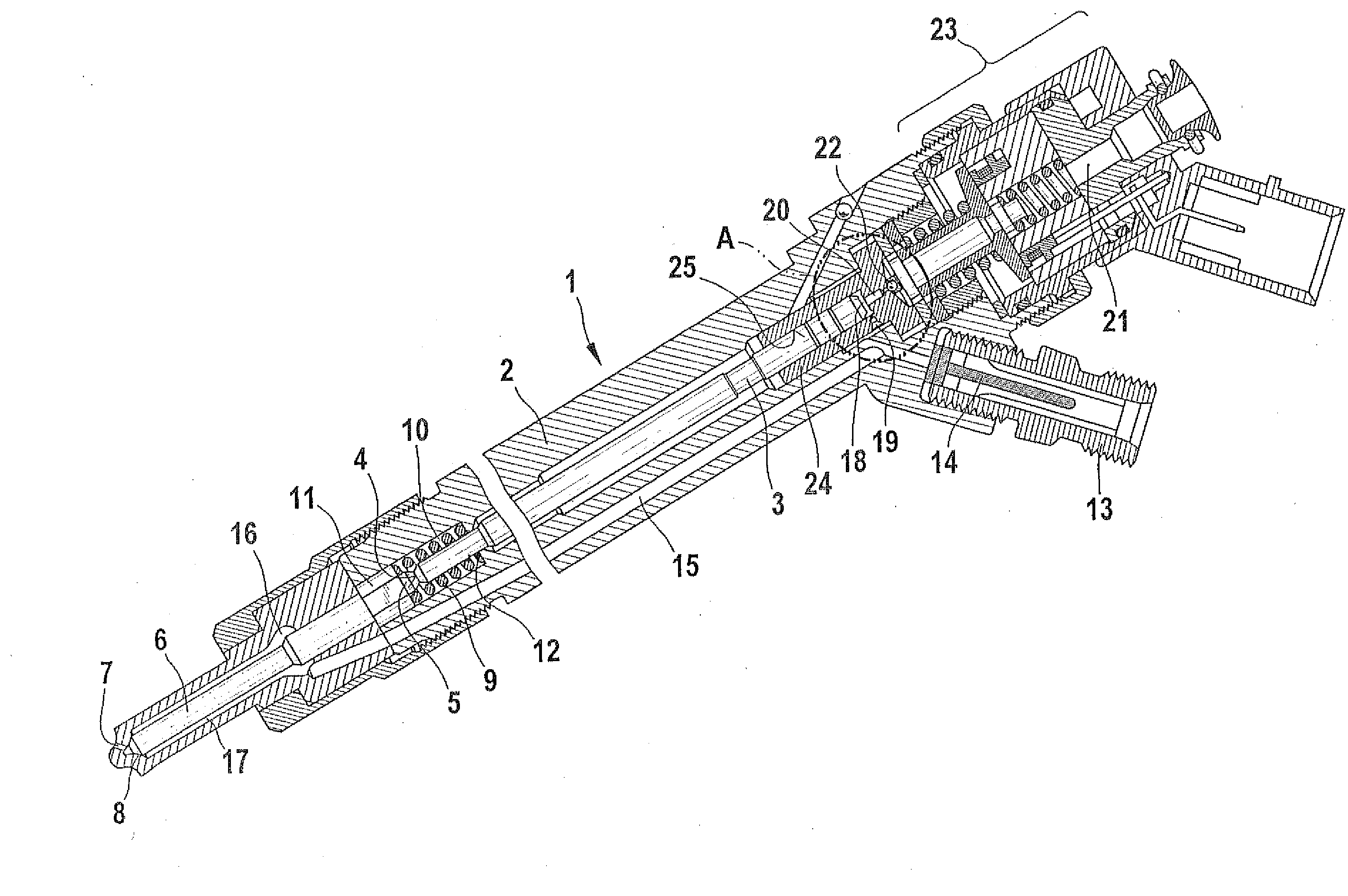
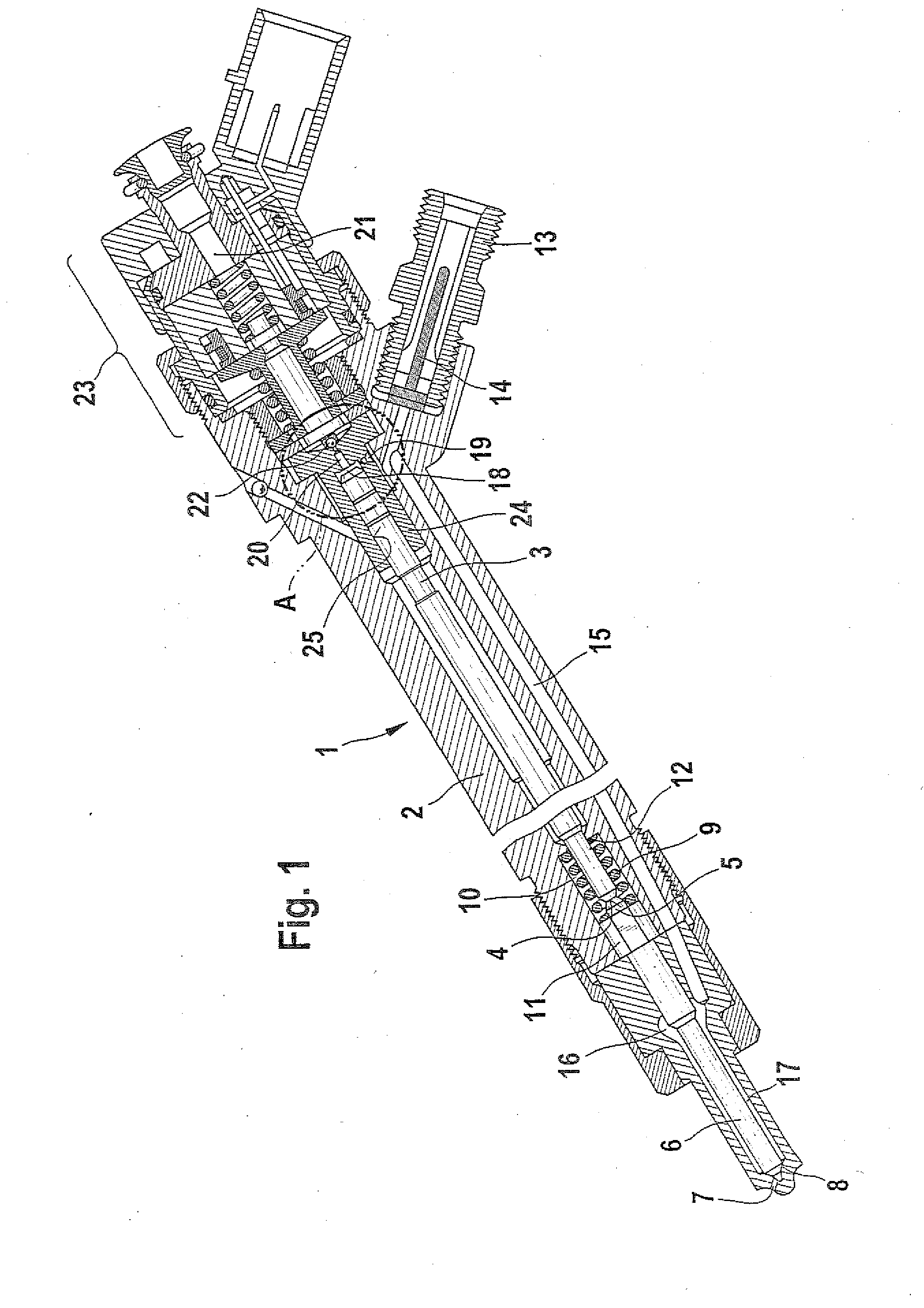
[0018]FIG. 1 shows a fuel injector for a high-pressure accumulator injection system.

[0019] A fuel injector 1 includes an injector body 2 in which a valve piston 3 is guided. With an end surface 4, the valve piston 4 acts on a pressure pin 5, which is embodied on a nozzle needle 6. At the end oriented toward a combustion chamber, not shown here, at least one injection opening 7 is provided in the injector body 2. When the injection opening 7 is closed, the end surface 4 of the valve piston 3 exerts a compressive force on the pressure pin 5 of the nozzle needle 6. In so doing, the nozzle needle 6 is moved into a seat 8 and thus, the at least one injection opening 7 is closed. In addition to the compressive force of the valve piston 3 on the pressure pin 5, a spring element 9 embodied in the form of a compression spring acts on the nozzle needle 6. The spring element 9 embodied as a compression spring is preferably a helical spring. In the embodiment form shown in FIG. 1, this...


PUM


Abstract

The invention relates to a method for manufacturing a fuel injector for an internal combustion engine that has a control valve, which opens or closes an outlet throttle from a control chamber and in which a closing element is moved into a valve seat in order to close the outlet throttle. The valve seat is produced by punch-forming using a forming punch. The invention also relates to a fuel injector that is manufactured in accordance with this method.

Description

TECHNICAL FIELD [0001] In fuel injected internal combustion engines, the fuel is supplied to the individual combustion chambers via fuel injectors with hydraulically actuated nozzle needles. To this end, the fuel injector is provided with a valve, which is triggered, for example, electromagnetically or by means of a piezoelectric actuator. The valve opens or closes an outlet throttle of the control chamber that is connected to the nozzle needle. PRIOR ART [0002] In fuel injectors of the kind known from the prior art, the housing of the fuel injector contains a valve component, which in turn contains an outlet throttle connected to a control chamber. A closing element opens or closes the outlet throttle. To this end, the valve component contains a conical valve seat into which the outlet throttle feeds. A spherical closing element is positioned in the conical valve seat in order to close the outlet throttle. [0003] To achieve the high opening and closing speeds of the fuel injector r...

Claims


Application Information

Patent Timeline
IPC IPC(8): F02M61/16
CPCF02M47/027F02M63/0077F02M63/0036F02M61/168
Inventor RUECKLE, MARKUSSCHNAUFER, AXELLEICHT, JOACHIM
Owner ROBERT BOSCH GMBH
Why Eureka
Try Eureka