Capacitive Vibration Sensor and Method for Manufacturing Same

a capacitive vibration and sensor technology, applied in the direction of subaqueous transducers, semiconductor electrostatic transducers, instruments, etc., can solve the problems of hysteresis and difficulty in miniaturizing capacitor-type microphones, and achieve the effect of minimizing the capacitive vibration sensor

Active Publication Date: 2007-11-15
MMI SEMICON CO LTD
View PDF8 Cites 56 Cited by
  • Summary
  • Abstract
  • Description
  • Claims
  • Application Information

AI Technical Summary

Benefits of technology

[0009] The present invention relates to a capacitive vibration sensor constituted by a vibration electrode plate and an opposing electrode plate, and its objective is to further miniaturize the capacitive vibration sensor to be m

Problems solved by technology

As a result, the conventional structure makes it difficult to miniaturize the capacitor-type microphone 21.
However, in the case of the microphone that is not used for measuring the absolute p

Method used


Image

  • Capacitive Vibration Sensor and Method for Manufacturing Same
  • Capacitive Vibration Sensor and Method for Manufacturing Same
  • Capacitive Vibration Sensor and Method for Manufacturing Same

Examples


embodiment 1

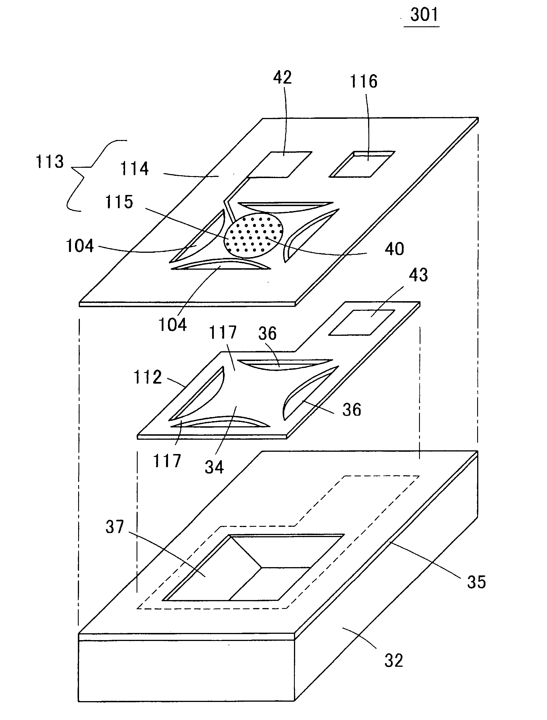
[0072]FIG. 3 is a schematic exploded perspective view that shows a capacitive vibration sensor 301 in accordance with embodiment 1 of the present invention. FIG. 4 is a plan view of the capacitive vibration sensor 301, and FIG. 5 is a cross-sectional view of the capacitive vibration sensor 301. Moreover, FIGS. 6(a), 6(b) and 6(c) are plan views that respectively show an opposing electrode plate 113, a vibration electrode plate 112 and a silicon substrate 32.

[0073] The capacitive vibration sensor 301 has a structure in which: a vibration electrode plate 112 is formed on an upper face of a silicon substrate 32, with an insulating coat film 35 interposed in between, and an electrode pad 43 used for extracting a detection signal of a sensor is provided on the upper face thereof, and an opposing electrode plate 113 is formed on the vibration electrode plate 112 located on a concave section 37 with a space interposed in between, and an electrode pad 42, used for extracting a detection si...

embodiment 2

[0108] FIGS. 16(a) and 16(b) are plan views that show an opposing electrode plate 113 and a vibration electrode plate 112 to be used in a capacitive vibration sensor in accordance with embodiment 2 of the present invention. In embodiment 2, with the etching hole 36 of the vibration electrode plate 112 being maintained in a semi-elliptical shape, the etching hole 104 of the opposing electrode plate 113 is formed into a slit shape having a semi-elliptical arc shape.

[0109] In the capacitive vibration sensor 301 of embodiment 1, since the etching hole 104 of the opposing electrode plate 113 has the same size as that of the etching hole 36 of the vibration electrode plate 112, the opposing electrode plate 113 might also be vibrated by a sound pressure. Moreover, since a fluid directly passes from the etching hole 104 of the opposing electrode plate 113 toward the etching hole 36 of the vibration electrode plate 112 to cause a reduction in fluid resistance within the low frequency band, ...

embodiment 3

[0111] FIGS. 17(a) and 17(b) are plan views that show an opposing electrode plate 113 and a vibration electrode plate 112 to be used in a capacitive vibration sensor in accordance with embodiment 3 of the present invention. In embodiment 3, with the etching hole 36 of the vibration electrode plate 112 being maintained in a semi-elliptical shape, the etching hole 104 of the opposing electrode plate 113 is allowed to have a length of ½ of that of embodiment 2.

[0112] In embodiment 3 having this structure, the etching of the concave section 37 proceeds as indicated in FIGS. 18(a) and 18(a′), FIGS. 18(b) and 18(b′), FIGS. 18(c) and 18(c′), as well as FIGS. 18(d) and 18(d′). FIG. 18(a) is a plan view that shows a capacitive vibration sensor in accordance with embodiment 3, FIGS. 18(b) to 18(d) are plan views that show the silicon substrate 32, and each of FIGS. 18(a′) to 18(d′) shows a cross section of the capacitive vibration sensor taken along line A-A of each of FIGS. 18(a) to 18(d). ...


PUM

PropertyMeasurementUnit
Shapeaaaaaaaaaa
Areaaaaaaaaaaa
Electric propertiesaaaaaaaaaa

Abstract

A vibration electrode plate 112 is formed on the upper face of a silicon substrate 32 with an insulating coat film 35 interposed in between. An opposing electrode plate 113 is placed on the vibration electrode plate 112 with an insulating coat film interposed in between, and acoustic holes 40 are opened through the opposing electrode plate 113. Etching holes 36 and 104, each having a semi-elliptical shape, are opened through the vibration electrode plate 112 and the opposing electrode plate 113 so as to face each other longitudinally. A concave section 37 having a truncated pyramid shape is formed in the upper face of the silicon substrate 32, by carrying out an etching process through the etching holes 36 and 104. The vibration electrode plate 112 is held in the silicon substrate 32 by a holding portion 112 placed between the etching holes 36.

Description

TECHNICAL FIELD [0001] The present invention relates to a capacitive vibration sensor and a manufacturing method thereof, and more specifically, relates to a capacitive vibration sensor for detecting vibrations, such as a sound wave transmitted through a medium such as air and water, and a manufacturing method thereof. BACKGROUND ART [0002] FIGS. 1(a), 1(b) and 1(c) are views for explaining a general principle of a capacitor-type microphone which is one type of vibration sensors. A capacitor-type microphone 11 has a structure in which an opposing electrode plate 12 and a vibration electrode plate 13 are aligned face to face with each other with a small gap, with a dc voltage being applied between the two electrode plates 12 and 13 by a dc power supply 14. The opposing electrode plate 12 is allowed to have sufficient rigidity, or secured so as not to vibrate, and the vibration electrode plate 13 is made thinner in thickness so as to be vibrated by sound vibrations. [0003] In this str...

Claims


Application Information

Patent Timeline
IPC IPC(8): G10K15/04C03C25/68H04R23/00
CPCA61B2562/0204G01H11/06H04R1/222H04R1/44H04R7/20H04R19/005H01L2224/48091H01L2924/10253H01L2224/48227H01L2924/00014H01L2924/00
Inventor KASAI, TAKASHIKATO, FUMIHITOIMAMOTO, HIROSHISATO, FUMIHIKOMUNECHIKA, MASAKITAKAHASHI, TOSHIYUKI
Owner MMI SEMICON CO LTD
Why Eureka
Try Eureka