Coherent Light Source and Optical System

a light source and optical system technology, applied in semiconductor lasers, instruments, record information storage, etc., can solve the problems of shortening the life of the laser, affecting the output property, and limited wavelengths of coherent light sources which can be used, so as to reduce the emission wavelength and reduce the emission efficiency , the effect of stably operating for a long period of tim

Active Publication Date: 2007-11-15
PANASONIC CORP
View PDF7 Cites 19 Cited by
  • Summary
  • Abstract
  • Description
  • Claims
  • Application Information

AI Technical Summary

Benefits of technology

[0039] According to the present invention, since the functional film is provided on such an irradiation surface, and a portion where the extraneous matter deposits due to irradiation of the first light can be irradiated with the second light, the extraneous matter can be removed efficiently.
[0040] According to the structure of the coherent light source of the present invention, a light source having the photocatalytic effect with the limitations on the emission wavelength being relaxed can be provided. Further, another aspect of the present invention can provide an optical system having the photocatalytic effect with the limitations on the emission wavelength being relaxed.
[0041] As an additional effect, a light emitting element which can stably operate for a long period of time can be realized. As another additional effect, a stable operation of a system such as an optical discs using short wavelength light sources or an optical system such as a laser display using visible light can be realized.

Problems solved by technology

Such a semiconductor laser suffers from a problem that dust and mold may adhere to a surface of the laser package and affect an output property.
In such a solid-state laser, dust attached to laser end surfaces causes deterioration of an outputting property and shortens the life of the laser.
For activating the photocatalytic functions, wavelengths of the coherent light sources which can be used are limited.
Thus, there is a problem that coherent light sources which can utilize a photocatalyst are limited to light sources with a short wavelengths of 390 nm or shorter.

Method used


Image

  • Coherent Light Source and Optical System
  • Coherent Light Source and Optical System
  • Coherent Light Source and Optical System

Examples


embodiment 1

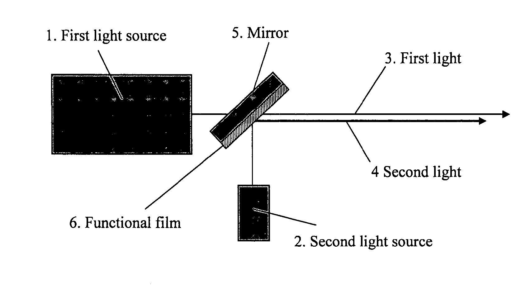
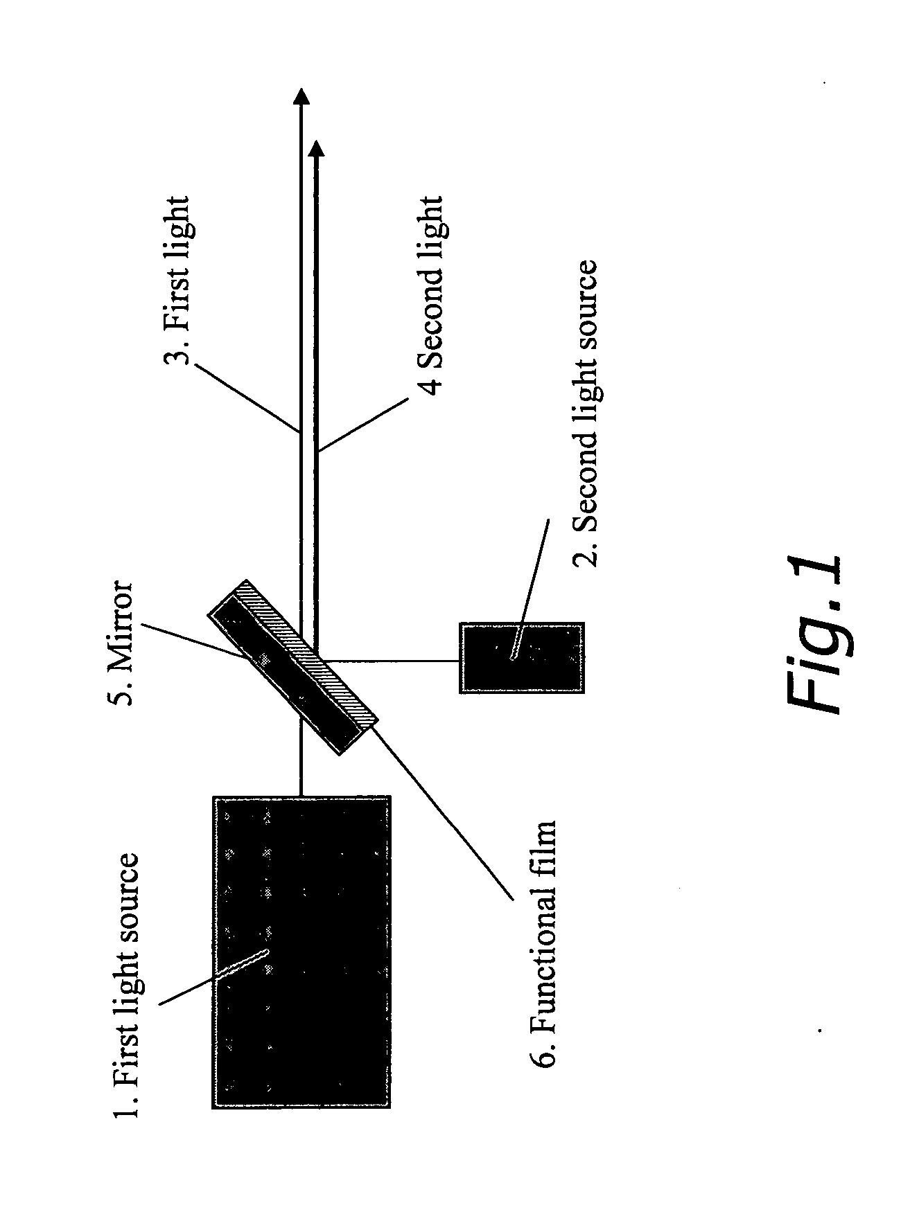
[0054]FIG. 1 is a diagram showing a structure of a coherent light source according to an embodiment of the present invention. As shown in FIG. 1, first light 3 emitted from a first light source 1 is multiplexed with second light 4 emitted from a second light source 2 by a mirror 5. On a surface of the mirror 5, a functional film 6 is formed. The first light source may be, for example, a GaN semiconductor laser with a wavelength of 410 nm. The second light source may be, for example, a GaN semiconductor laser with a wavelength of 380 nm.

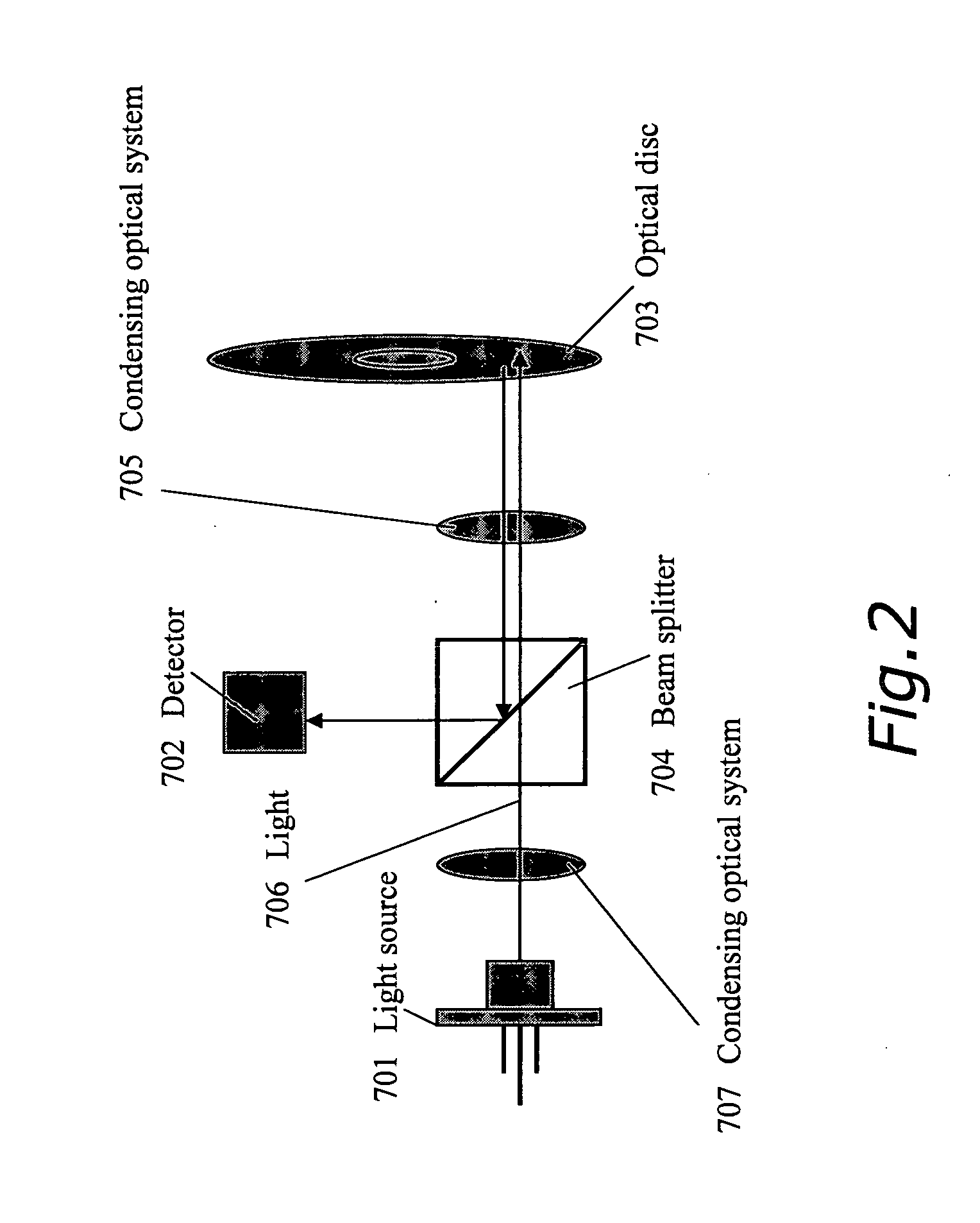
[0055] As an example of an optical system using this light source, FIG. 2 shows an optical disc apparatus to which such a light source is applied. In FIG. 2, a light source 701 is a packaged coherent light source as shown in FIG. 1. Light 706 emitted from the light source 701 passes through a condensing optical system 707, a beam splitter 704, a condensing optical system 705, and impinges upon an optical disc 703. Reflected light is reflected off the...

embodiment 2

[0068] Another example of the coherent light source according to the present invention will be described with reference to FIG. 3. In this example, a solid-state laser is used as a main body of the light source.

[0069] Solid-state lasers excited by semiconductor lasers, particularly, those formed of a solid laser material doped with ions such as Nd, Cr, and the like, are widely used. In FIG. 3, a YAG laser doped with Nd, which is typically used, is shown as a light source main body. A semiconductor laser 402 for exciting a solid-state laser irradiates a solid-state laser medium 403 (YAG laser medium) with light having a wavelength of 808 nm. The solid-state laser medium is resonated by a resonator mirror 405 and performs laser oscillation. Laser oscillation mainly outputs infrared light having a wavelength of 1.064 μm, but the output has a high outputting property of few watts to several tens of watts or higher.

[0070] In the case where such a solid-state laser is used, there is als...

embodiment 3

[0097] The coherent light source according to the present invention which employs a GaN semiconductor laser will be described with reference to FIG. 6.

[0098] The GaN semiconductor laser realizes oscillation wavelength of 360 nm to 480 nm and can even generate light in the wavelength range of 500 nm or longer. The output power has been increased as well, and an optical output of several tens of milliwatt is possible.

[0099] In a GaN semiconductor laser at a wavelength of 400 nm or longer, there is a problem of deposition of foreign substances in a window portion of a laser package where laser light is focused and a portion which receives light with high power density in an optical system employing the laser. In order to solve this problem, the structures shown in FIG. 6 are proposed.

[0100]FIG. 6(a) shows a structure of a semiconductor laser package. A semiconductor laser 300 is soldered to a submount 302 provided on a base 303. A wavelength of a part of first light 309 output from ...


PUM

PropertyMeasurementUnit
wavelengthaaaaaaaaaa
reflectanceaaaaaaaaaa

Abstract

An object of the present invention is to provide a coherent light source with limitations on the wavelength of emitted light being relaxed. The coherent light source of the present invention is a coherent light source for simultaneously emitting a first light (3) and a second light (4) having a wavelength shorter than that of the first light (3), including: a light source main body emitting at least the first light (3); a mirror (5) which transmits or reflects the first light (3); and a functional film (6) provided on at least a part of the mirror (5). The functional film (6) has a photocatalytic effect to be induced by the second light (4).

Description

TECHNICAL FIELD [0001] The present invention relates to a coherent light source and an optical system, particularly to a coherent light source and an optical system including a functional film which produces a photocatalytic effect. BACKGROUND ART [0002] A semiconductor laser consisting of III-V nitride semiconductor material (AlxGayIn1-x-yN (herein, 0≦x≦1, and 0≦y≦1)) such as gallium nitride is a key device for realizing ultra-high density recording on an optical disc and is a blue violet semiconductor laser which is at a level closest to a practical use. Increasing an output of such a blue violet semiconductor laser allows not only rapid writing on optical discs but also application to laser displays. This is an essential technology for developing a new technical field. [0003] In optical disc systems of a recording and reproduction type, a semiconductor laser with a high output is desirable. As an effective way to increase an output, a method to render reflectances of end surfaces...

Claims


Application Information

Patent Timeline
Patent Type & Authority Applications(United States)
IPC IPC(8): H01S3/10G02B27/00G02F1/37H01S3/00H01S3/02H01S3/067H01S3/094H01S3/109H01S3/23H01S5/00H01S5/02H01S5/022
CPCG02B27/0006H01S5/4087G11B7/1275G11B7/1362G11B7/1395H01S3/005H01S3/0092H01S3/025H01S3/0809H01S3/09415H01S3/109H01S3/2391H01S5/005H01S5/0092H01S5/02212H01S5/02296H01S5/32341H01S5/4031G11B7/1201G11B7/121G02B1/18H01S5/02257
Inventor MIZUUCHI, KIMINORIYAMAMOTO, KAZUHISAKASAZUMI, KEN'ICHIKIDOGUCHI, ISAOKITAOKA, YASUO
Owner PANASONIC CORP
Why Eureka
Try Eureka