
Radio transmission method, radio reception method, radio transmission apparatus and radio reception apparatus

Inactive Publication Date: 2007-11-15
FUJITSU LTD
View PDF20 Cites 55 Cited by
  • Summary
  • Abstract
  • Description
  • Claims
  • Application Information

AI Technical Summary

Benefits of technology

[0063]The present invention has been developed in consideration of the above-mentioned problems, and it is therefore an object of the invention to, when a waveform shaping filter is applied with respect to a pilot signal and a data signal which have different occupied bands, avoid mapping a pilot signal having a low quality or a pilot signal different in channel distortion from the data signal in a portion of the occupied band of the data signal, thereby enhancing the data signal demodulation capability (channel estimation accuracy and channel compensation accuracy) so as to improve the data signal reception characteristic while suppressing the PAPR.
[0075]The above-described present invention can provide at least one of the following effects and advantages.
[0076](1) In a case in which a data signal is transmitted through the use of a partial band of a frequency band for the transmission of a pilot signal, the pilot signal (replica on the reception side) to be transmitted through the use of at least the partial band and the data signal are waveform-shaped to have the same shape in a frequency domain, thereby mapping a pilot signal whose amplitude does not attenuate due to the waveform shaping or a pilot signal equal in channel distortion to a data signal with respect to all the effective frequencies of the data signal. This can enhance the demodulation processing capability (channel estimation accuracy and channel compensation capability) on the data signal on the reception side while suppressing the PAPR of a transmission signal, which improves the reception characteristic.
[0078](3) Still additionally, the waveform shaping on the data signal and the pilot signal in the aforesaid partial band is conducted in a frequency domain, which enables the waveform shaping to be easily realized with respect to arbitrary bands.

Problems solved by technology

That is, for example, at the right-side end (higher frequency side) of an occupied band of a data signal, a pilot signal with a low quality (S / N), whose amplitude attenuates due to the waveform shaping filter 119, is mapped with respect to a portion of the effective subcarriers, which can degrade the channel estimation accuracy and deteriorate the reception characteristic.
On the other hand, at the left-side end (lower frequency side) of the occupied band of the data signal, with respect to a portion of the subcarriers, a channel distortion due to devices including the waveform shaping filters 117-i and 119 differs between the data signal and the pilot signal, which can cause incorrect channel compensation for the data signal and deteriorate the reception characteristic of the data signal.

Method used


Image

  • Radio transmission method, radio reception method, radio transmission apparatus and radio reception apparatus
  • Radio transmission method, radio reception method, radio transmission apparatus and radio reception apparatus
  • Radio transmission method, radio reception method, radio transmission apparatus and radio reception apparatus

Examples


Embodiment Construction

[A] Description of an Embodiment

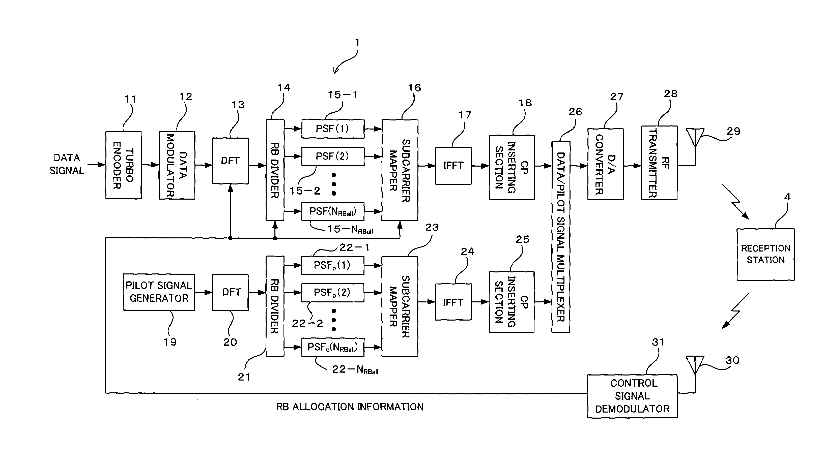
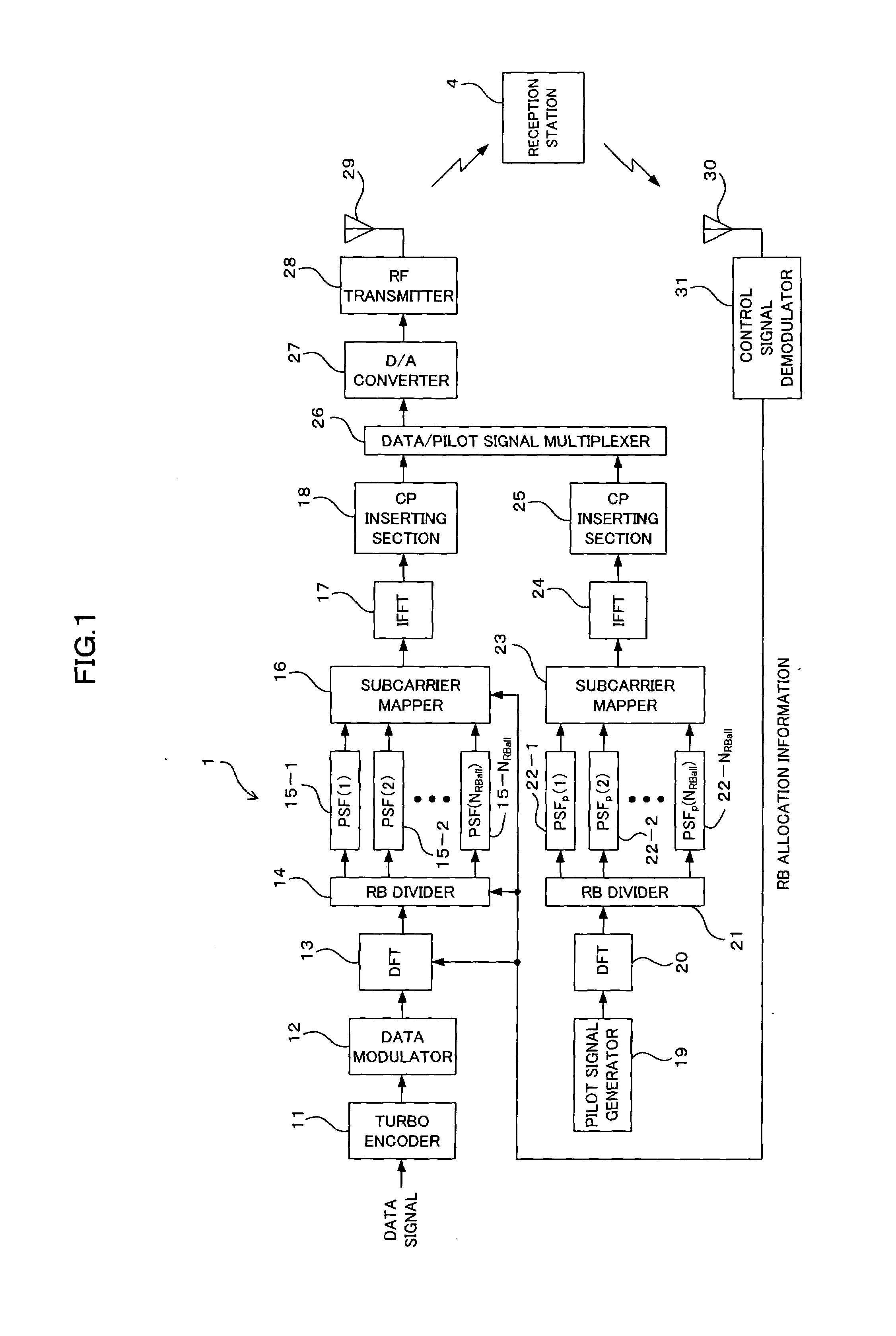
[0098]FIGS. 1 and 4 are block diagrams showing, as a radio communication system according to an embodiment of the present invention, a configuration of a system employing a DFT-Spread OFDM which is one of single carrier transmission modes, and FIG. 1 is a functional block diagram taking note of a configuration of a transmission station (radio transmission apparatus) 1 while FIG. 4 is a functional block diagram taking note of a configuration of a reception station (radio reception apparatus) 4. As described above with reference to FIGS. 10(A), 10(B) and 12, this embodiment is also based upon an FDMA communication mode in which a system frequency band is divided by a fixed band (RB) and a data signal is transmitted in units of the bands, the number of which is set arbitrarily, while a pilot signal is transmitted in a distributed arrangement fashion throughout the entire system frequency band. Incidentally, in FIGS. 1 and 4, point-to-point communications...


PUM


Abstract

A pilot signal is transmitted with a predetermined frequency band and a data signal is transmitted with a partial band of the frequency band, and the pilot signal and the data signal to be transmitted with at least the partial band, are controlled its waveform to have the same waveforms in a frequency domain. Thus, in the case of controlling waveforms of the pilot signal and the data signal which have different occupied bands, it is possible to, in a portion of the occupied band for the data signal, avoid the mapping of a low-quality pilot signal or the like, enhance the data signal demodulation capability and improve the data signal reception characteristic while suppressing PAPR.

Description

CROSS REFERENCE TO RELATED APPLICATIONS[0001]This application is based on and hereby claims priority to Japanese Application No. 2006-130396 filed on May 9, 2006 in Japan, the contents of which are hereby incorporated by reference.BACKGROUND OF THE INVENTION[0002](1) Field of the Invention[0003]The present invention relates to a radio transmission method, radio reception method, radio transmission apparatus and radio reception apparatus and, for example, it relates to a technique suitable for use in a next-generation mobile communication system employing a DFT (Discrete Fourier Transform)-Spread OFDM (Orthogonal Frequency Division Multiplexing) method which is one of radio access modes.[0004](2) Description of the Related Art[0005]In a next-generation mobile communication system, as the principal characteristics (necessary conditions) needed for radio access modes with respect to an uplink from a mobile terminal (MS : Mobile Station) to a base station (BTS : Base Transceiver Station...

Claims


Application Information

Patent Timeline
IPC IPC(8): H04K1/10H04J1/00H04J11/00H04L27/01
CPCH04L25/03834H04L27/2647H04L27/2636H04L27/2613H04L27/26132H04L5/0048H04L27/261H04L27/2614
Inventor JITSUKAWA, DAISUKESEKI, HIROYUKI
Owner FUJITSU LTD
Learn More