Bio-Electronic Device

a biomolecule and electronic device technology, applied in the field of biomolecule detection, can solve the problems of low control over the molecular recognition (sensing) conditions and relatively slow process, and achieve the effect of enabling frequency modulated biomolecular interaction control

Inactive Publication Date: 2007-11-15
INST DE ENGENHARIA DE SISTEMAS E COMPUTADORES PARA OS MICROSISTEMAS E AS NANOTECHAS +1
View PDF2 Cites 15 Cited by
  • Summary
  • Abstract
  • Description
  • Claims
  • Application Information

AI Technical Summary

Benefits of technology

[0006] According to the invention, there is provided a bioelectronic device comprising a current carrying conductor and an electromagnet enabling frequency modulated biomolecular interaction control via the application of varying magnetic fields to magnetically labelled biomolecules.

Problems solved by technology

However, present biosensor and biochip devices (based on different types of sensor) utilise either: conventional (slow, diffusion-controlled) liquid phase molecular recognition reaction conditions (such as nucleic acid hybridisation conditions in DNA microarrays), which are fixed for any one detection experiment; or they employ electric fields to enhance the rates of biomolecular immobilisation or hybridisation processes by charge effects, primarily to reduce assay times. These techniques offer little control over the molecular recognition (sensing) conditions, other than changing the pH, salt or chemical composition of the sample medium (usually an aqueous phase buffering medium) by fluid flow.
This is also a relatively slow process.

Method used


Image

  • Bio-Electronic Device
  • Bio-Electronic Device
  • Bio-Electronic Device

Examples


examples

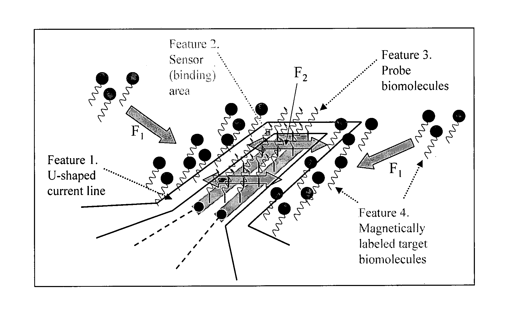
[0056] A sensor-free chip was fabricated with U-shaped current lines to demonstrate the “proof of principle” of the device using DNA-DNA hybridisation (i.e. the binding of a DNA probe with a complementary magnetically labelled DNA target) as a model for the use of the invention to (i) perform a rapid DNA hybridisation experiment and (ii) effect a frequency manipulated biomolecular recognition process.

Chip and Probe Preparation

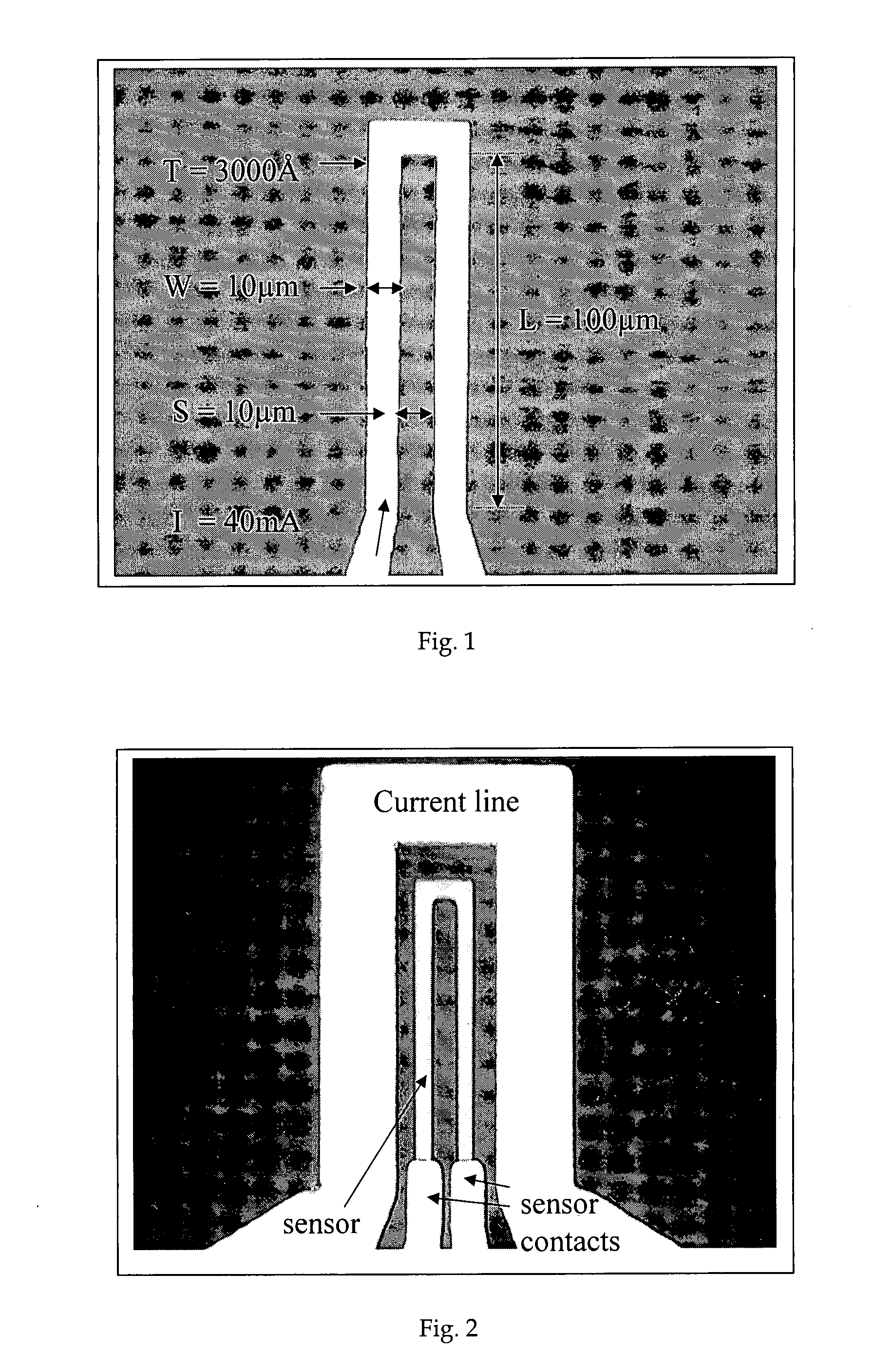
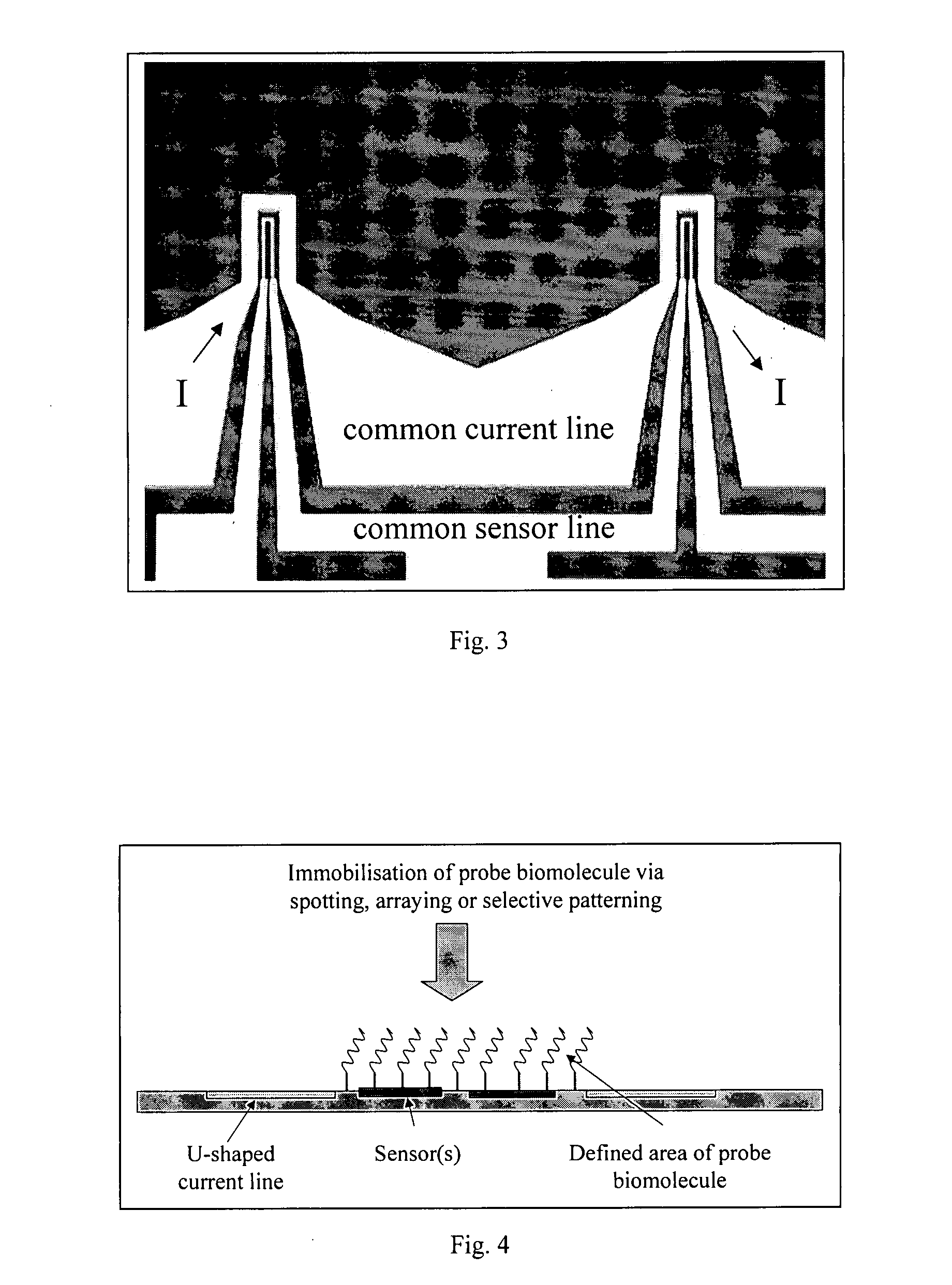
[0057] The on-chip U-shaped current line structures were fabricated with dimensions (FIG. 1) 100 μm long, 10 μm wide and 3000 Å thick with a space between the arms of the U-shaped line of 10 μm and passivated (covered) with a layer of silicon dioxide of 2000 Å. Probe DNA molecules (50mer oligonucleotides corresponding to a specific sequence in the cystic fibrosis transmembrane regulator (CFTR) gene, where the most common cystic fibrosis mutation delF508 occurs) were immobilised across the full chip surface. The chip was placed within the electronic set-up (a...


PUM


Abstract

A bioelectronic device comprising a current carrying conductor and an electromagnet enabling frequency modulated biomolecular interaction control via the application of varying magnetic fields to magnetically labelled biomolecules. The device further comprises a magnetoresistive sensor located in proximity to the said conductor and carrying on its surface probe molecules. The device enables reducing assay times by using said magnetic field generating current carrying conductor in combination with an external oscillating magnetic field generator (electromagnet).

Description

INTRODUCTION [0001] The invention relates to detection of biomolecules. [0002] It is known to provide a magnetic field sensor to detect magnetically labelled biomolecules. However, present biosensor and biochip devices (based on different types of sensor) utilise either: conventional (slow, diffusion-controlled) liquid phase molecular recognition reaction conditions (such as nucleic acid hybridisation conditions in DNA microarrays), which are fixed for any one detection experiment; or they employ electric fields to enhance the rates of biomolecular immobilisation or hybridisation processes by charge effects, primarily to reduce assay times. These techniques offer little control over the molecular recognition (sensing) conditions, other than changing the pH, salt or chemical composition of the sample medium (usually an aqueous phase buffering medium) by fluid flow. This is also a relatively slow process. Ferreira H A et al., “Biodetection using magnetically labelled biomolecules and ...

Claims


Application Information

Patent Timeline
Patent Type & Authority Applications(United States)
IPC IPC(8): B01J19/08
CPCG01N33/54373G01N27/745
Inventor GRAHAM, DANIEL LEONARD VINCENTTEIXEIRA DUARTE FERREIRA, HUGO ALEXANDREDA CONCEICAO DIAS MARQUES FELICIANO, NUNO FILIPEPEIXEIRO DE FREITAS, PAULO JORGEGALVIN, PAUL TIMOTHY
Owner INST DE ENGENHARIA DE SISTEMAS E COMPUTADORES PARA OS MICROSISTEMAS E AS NANOTECHAS
Why Eureka
Try Eureka