Mea-Gasket Assembly and Polymer Electrolyte Fuel Cell Using Same

Inactive Publication Date: 2007-11-15
PANASONIC CORP
View PDF8 Cites 55 Cited by
  • Summary
  • Abstract
  • Description
  • Claims
  • Application Information

AI Technical Summary

Benefits of technology

[0050] As has been described hereinabove, the MEA-gasket assembly and the polymer electrolyte fuel cell using the same according to the invention have the effect of restraining the cross-leak of the oxidizing gas and the reducing gas at the diverging points where the gases diverge from the manif

Problems solved by technology

As a result, mixing of the oxidizing gas and the reducing gas, that is the so-called cross-leak phenomenon, occurs, which leads to a possibili

Method used


Image

  • Mea-Gasket Assembly and Polymer Electrolyte Fuel Cell Using Same
  • Mea-Gasket Assembly and Polymer Electrolyte Fuel Cell Using Same
  • Mea-Gasket Assembly and Polymer Electrolyte Fuel Cell Using Same

Examples


first embodiment

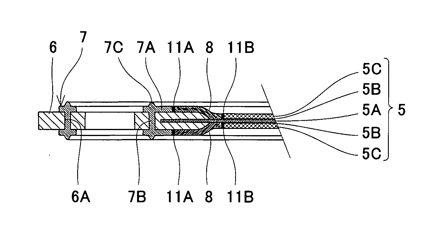
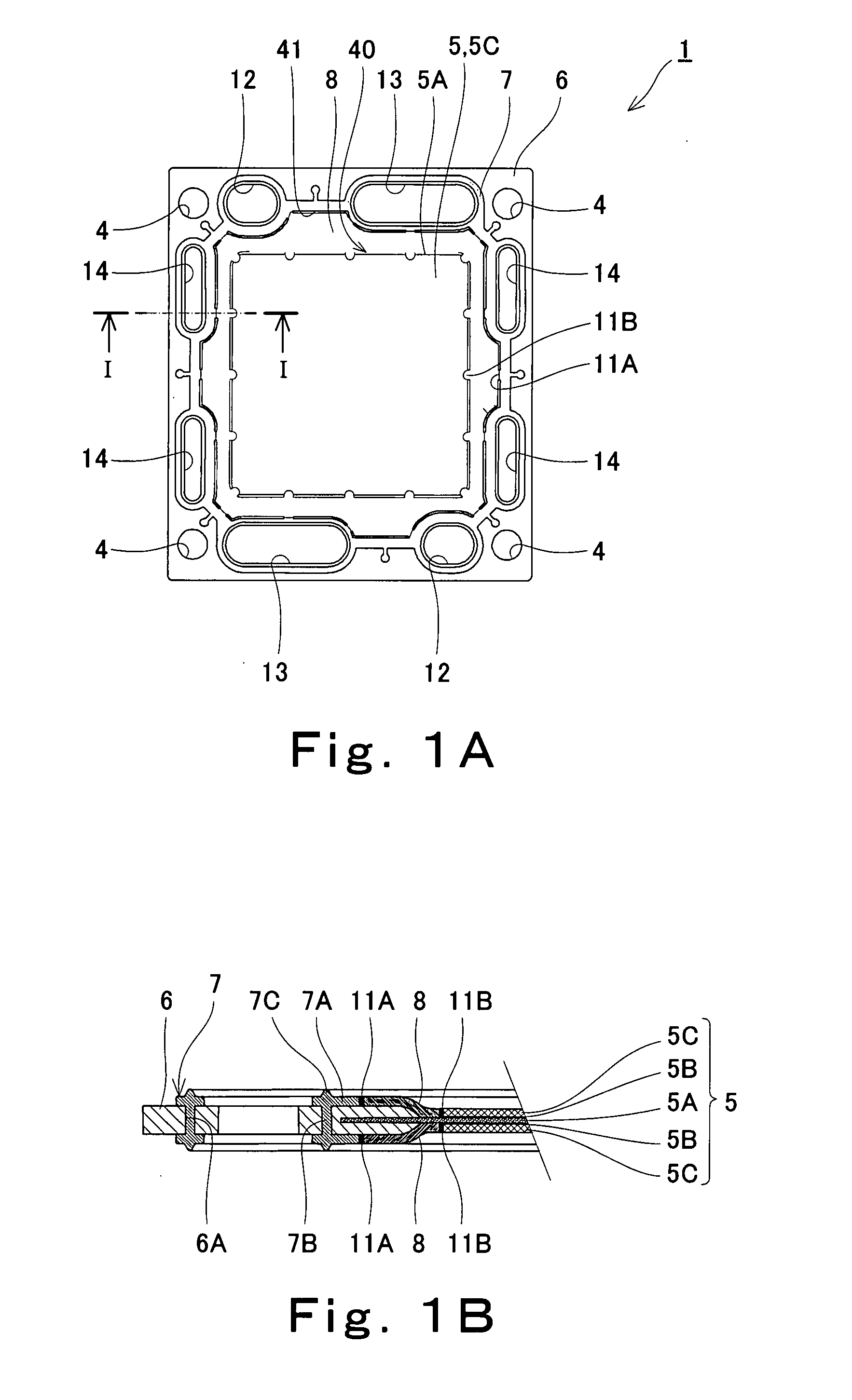
[0106]FIG. 1 is a view illustrating a structure of an MEA-gasket assembly according a first embodiment, wherein FIG. 1(a) is a plan view (cathode separator side) and FIG. 1(b) is a sectional view taken along line I-I of FIG. 1(a).

[0107] As illustrated in FIG. 1, the MEA-gasket assembly 1 of the first embodiment has an MEA 5. In the MEA 5, a catalyst layer 5B and a gas diffusing layer 5C are stacked in order on each surface of a part (inner part) of a polymer electrolyte membrane 5A, the part excluding the peripheral region (periphery) of the membrane 5A.

[0108] An annular frame 6 (in this embodiment, the frame takes the form of a substantially square plate) is provided so as to hold the peripheral region of the polymer electrolyte membrane 5A of the MEA 5 and to enclose the outer peripheral edge of the polymer electrolyte membrane 5A. Herein, the frame 6 is made of plastic resin. The frame 6 is disposed such that an annular gap is formed between the inner peripheral edge of the fra...

example 1

[0156] The following performance test was conducted on the polymer electrolyte fuel cell of the first embodiment.

[0157] 1. Cross Leak Resistance Test

[0158] The openings of the oxidizing gas manifolds of the polymer electrolyte fuel cell of the first embodiment were sealed. The reducing gas manifolds were pressurized to 0 to 200 KPa by use of dried nitrogen gas, and the amount of dried nitrogen gas leaking to the oxidizing gas manifolds was measured.

[0159] As a result, a leak of the dried nitrogen gas to the oxidizing gas manifolds was not detected even when the reducing gas manifolds were pressurized up to 200 KPa.

[0160] 2. Anode Pressure Loss Test

[0161] Dried nitrogen gas of 3 to 20 NL was allowed to flow in the reducing gas manifolds of the polymer electrolyte fuel cell of the first embodiment and the loss of pressure was measured.

[0162] As Comparative Example 1, a polymer electrolyte fuel cell was used which had the same structure as of the first embodiment except that the ...

second embodiment

[0171] The polymer electrolyte fuel cell of the second embodiment is the same as that of the first embodiment except the material of the frame of the MEA-gasket assembly 1; the shapes of the main faces of the MEA-gasket assembly 1, the anode separator 2 and the cathode separator 3; and the layout of the manifold holes. Therefore, in the second embodiment, only the points different from the first embodiment will be explained.

[0172]FIG. 11 is a plan view (anode separator side) showing a structure of the MEA-gasket assembly 1 of the second embodiment.

[0173] As the material of the frame 6, glass fiber containing polypropylene (produced by Idemitsu Petrochemical Co., Ltd. and marketed under the name of R350G) is used. The first gasket 1 is made of Santoprene 8101-55 (produced by Advanced Elastomer Systems), that is, a thermoplastic elastic material, similarly to the first embodiment. Since the first gasket 7 and the frame 6 both have polypropylene as a plastic component, the first gask...


PUM

PropertyMeasurementUnit
Pressureaaaaaaaaaa
Pressureaaaaaaaaaa
Pressureaaaaaaaaaa

Abstract

The invention provides an MEA-gasket assembly (1) comprising: an MEA (5) having a polymer electrolyte membrane (5A), catalyst layers and gas diffusing layers (5C); a plate-like frame (6) which is joined to a portion of the polymer electrolyte membrane (5A) so as to enclose the MEA (5), the portion being located in a peripheral region of the MEA (5) and which has a plurality of fluid manifold holes (12, 13, 14); and an annular gasket (7) formed on both faces of the frame (6), wherein an annular gap formed between the inner peripheral edge of the annular gasket (7) and the outer peripheral edges of the gas diffusing layers (5C) is at least partially closed.

Description

TECHNICAL FIELD [0001] The present invention relates to an MEA (Membrane-Electrode-Assembly)-gasket assembly and a polymer electrolyte fuel cell, and more particularly to an MEA-gasket assembly having manifold holes and a polymer electrolyte fuel cell using the same. BACKGROUND ART [0002]FIG. 16 is a partially exploded perspective view showing the structure of a prior art polymer electrolyte fuel cell. [0003] As illustrated in FIG. 16, the polymer electrolyte fuel cell 100 is composed of cells 10 stacked therein. [0004] Although not shown in FIG. 16, a current collecting plate, an insulating plate and an end plate are mounted on the outermost cells located at both ends of the cell stack 10. The cells 10 are fastened with fastening bolts that pass through bolt holes 4 and nuts (not shown). [0005] Each cell 10 is composed of an MEA-gasket assembly 1 that is sandwiched between a pair of separators, i.e., an anode separator 2 and a cathode separator 3 (herein, these are generically call...

Claims


Application Information

Patent Timeline
IPC IPC(8): H01M8/02
CPCH01M8/0254H01M8/0258H01M8/0267H01M8/0271H01M8/0273Y02E60/521H01M8/0284H01M8/0286H01M8/1004H01M8/242H01M8/0276Y02E60/50H01M8/2483
Inventor KOBAYASHI, SUSUMUSEKI, YASUHIRO
Owner PANASONIC CORP
Why Eureka
Try Eureka