Videolaryngostroboscope

a videolaryngostroboscope and ophthalmology technology, applied in endoscopes, medical science, surgery, etc., can solve the problems of impaired accuracy of vocal folds visualization with naked eyes, loss of observation ability of human eyes, and inability to capture images at frequencies higher than 30 hz, so as to improve the probability of cure, facilitate identification, and high frequency performance

a videolaryngostroboscope and ophthalmology technology, applied in endoscopes, medical science, surgery, etc., can solve the problems of impaired accuracy of vocal folds visualization with naked eyes, loss of observation ability of human eyes, and inability to capture images at frequencies higher than 30 hz, so as to improve the probability of cure, facilitate identification, and high frequency performance

US20070265504A1Inactive Publication Date: 2007-11-15OTT CIRO TIMOTEO

Image

  • Videolaryngostroboscope
  • Videolaryngostroboscope
  • Videolaryngostroboscope

Examples


Embodiment Construction

[0052] While the invention is susceptible of various modifications and alternative constructions, certain illustrated embodiments thereof have been shown in the drawings and will be described below in detail. It should be understood, however, that there is no intention to limit the invention to the specific form disclosed, but, on the contrary, the invention is to cover all modifications, alternative constructions, and equivalents falling within the spirit and scope of the invention as defined in the claims.

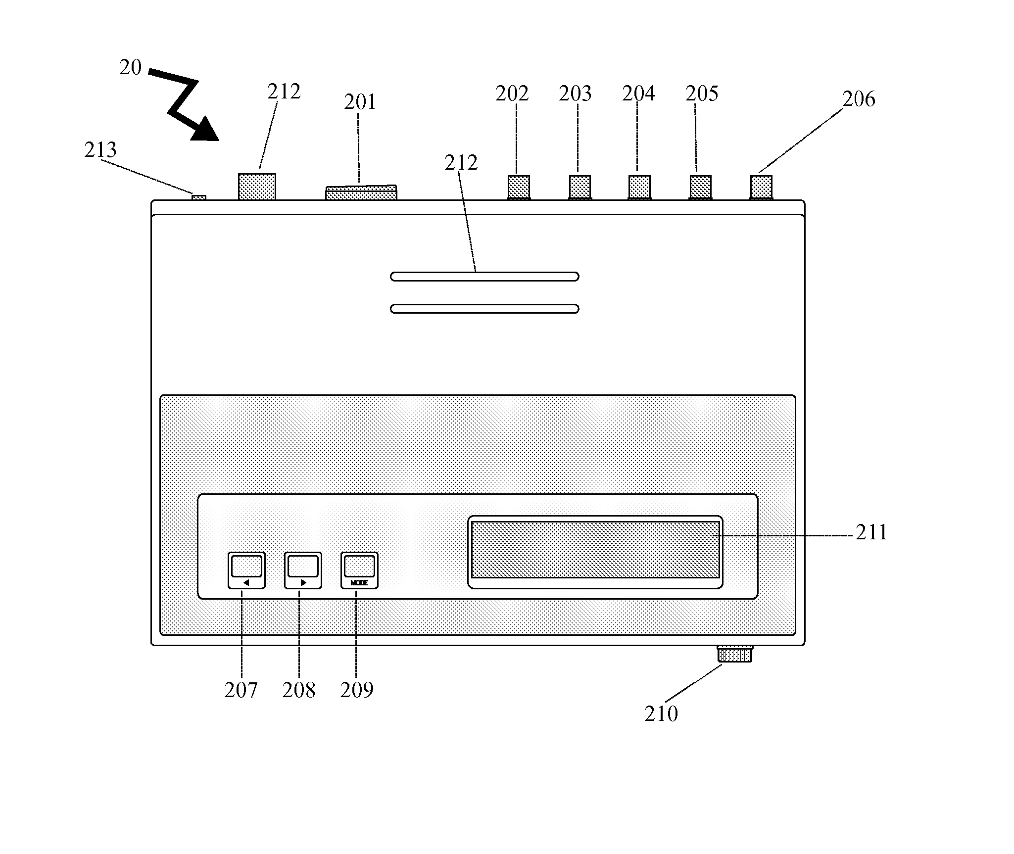
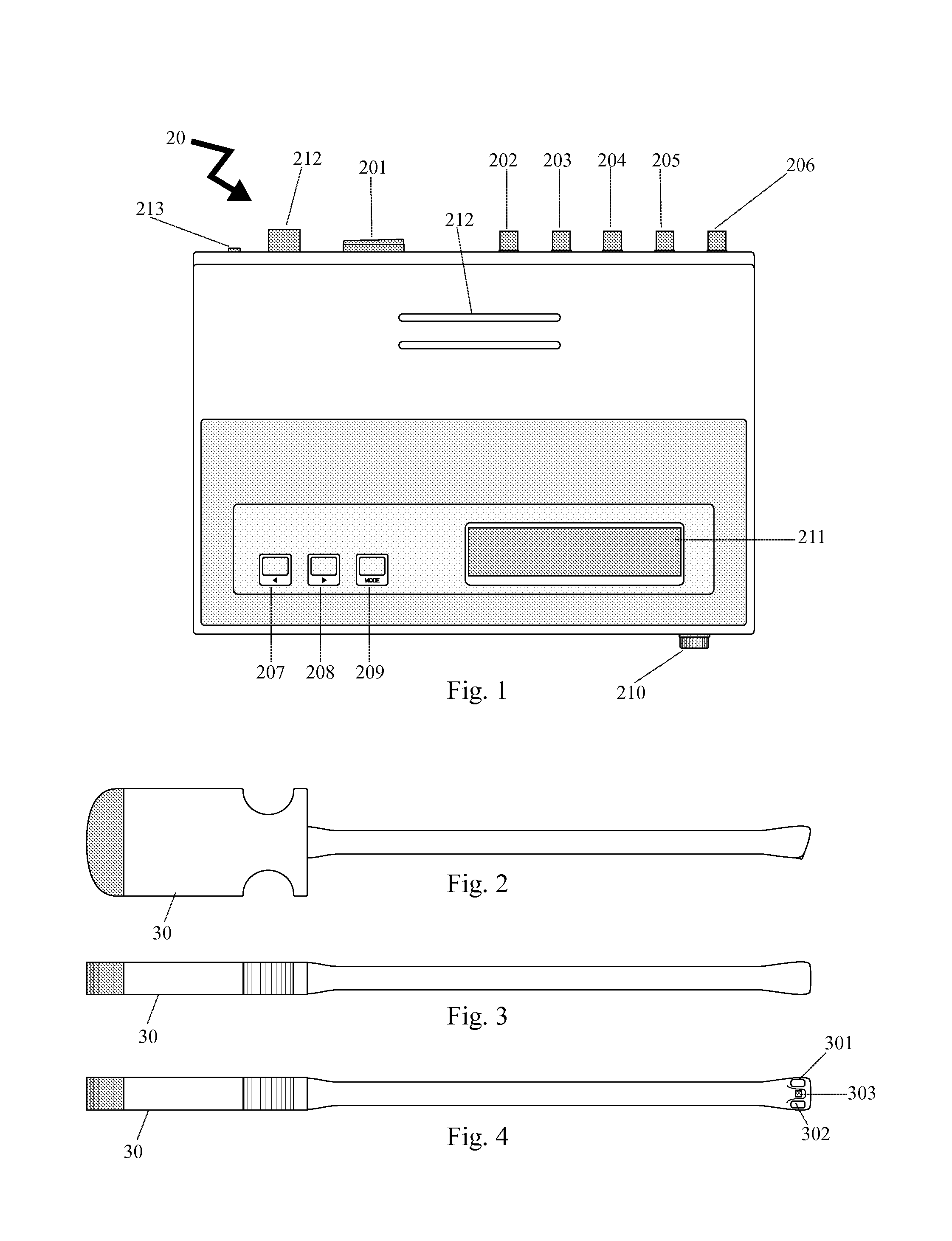
[0053] The present invention is a videolaryngostroboscope, and the following FIGS. 1-13 show various features and advantages of the present invention. Referring first now to FIG. 1, the present invention is made up of a processor base (20) that controls various peripherals including in the preferred embodiment the following:

[0054] 1. Externally, the processor base (20) is provided with command buttons, a liquid crystal display (211), and connections to auxiliary equipment and p...


PUM


Abstract

An innovative one-piece videolaryngostroboscope that provides slow motion visualization and detailed analysis of the vocal cords movements, which are imperceptible to the naked eye due, by means of a video camera with stroboscopic; said apparatus is used to perform examinations in patients, aiming to assess the incidence of larynx cancer. The invention including a processor base; an optics tube with a built-in light sources, a built-in video camera; a microphone, an auxiliary pedal and software.

Description

FIELD OF THE INVENTION [0001] The present invention relates to medical devices and more particularly, to an innovative videolaryngostroboscope whose field of application includes otorhinolaryngology. BACKGROUND OF THE INVENTION [0002] It is known that human's vocal cords are located in the larynx. For that reason, the aim of laryngoscopy is to examine the general state of the vocal folds, detecting from a simple failure in the production of sounds to tumors and other serious anomalies. However, in many larynx examinations, an accurate visualization of the vocal folds function with the naked eye is impaired due to the depth to which this organ is located, as well as the high frequency vibration of these vocal folds when sounds are produced. [0003] A variety of attempts have been made to perform this examination. One method has been to connect laryngoscopes to video cameras. However, due to the large size of these cameras, it was necessary to use a thin metal tube (called “optics tube...

Claims


Application Information

Patent Timeline
15 Nov 2007
Publication
US20070265504A1
IPC
A61B1/267; A61B1/06; A61B1/04
CPC
A61B1/05; A61B1/2673; A61B1/0684; A61B1/0676
Inventors
OTT, CIRO TIMOTEO