MR imaging providing tissue/blood contrast image

a contrast image and magnetic resonance imaging technology, applied in the field of magnetic resonance imaging, can solve the problems of blood flowing into a slice to be imaged suffering from a considerable amount of mt effects, the contrast between blood and parenchyma is not always fully satisfied, and the entire scanning process takes as long as 10 minutes, so as to reduce the apparent t1 relaxation time of blood, reduce the effect of mt effects given free water of blood flow and rapid return to their steady sta

Inactive Publication Date: 2007-11-15
TOSHIBA MEDICAL SYST CORP
View PDF23 Cites 27 Cited by
  • Summary
  • Abstract
  • Description
  • Claims
  • Application Information

AI Technical Summary

Benefits of technology

[0025] An object of the present invention to largely increase contrast between blood and parenchyma compared to the prior method by decreasing the influence of MT effects given blood, so that a higher depiction blood flow image or parenchyma image is gained in imaging by which a distinction is made by MT pulses between blood in motion and stationary blood and / or parenchyma.
[0044] By the above single-shot imaging, artifacts due to motions in the phase-encoding direction can be suppressed steadily. In addition, artifacts occurring in the slice-encoding direction can be reduced by employing in combination both the ECG gating and intermittent breath hold techniques. It is therefore possible to provide a three-dimensional image having higher value of resolution. When an T2-weighted image of a higher resolution value is obtainable, signals from the cardiac muscle and others can be suppressed by the MT pulse and signals from fat can also be suppressed by the fat-suppression pulse. This enables tissue contrasts between blood and the cardiac muscle and / or cardiac wall to raised greatly. Hence an effective imaging technique for the heart is available.

Problems solved by technology

However, in the case of the foregoing MR angiography making use of a slice-selective MT pulse, blood flowing into a slice to be imaged suffers from a considerably large amount of MT effects, because a flip angle given to magnetization when the MT pulse is applied is set to a greater amount (for example, 500 to 1000 degrees).
Therefore, contrast between blood and parenchyma is not always fully satisfied under recent needs for higher image resolution.
The entire scanning takes as long as 10 minutes, for example, imposing a greater burden on a patient.
On one hand, for depicting cardiac vascular systems, synchronization with the cardiac temporal phase, which is typically represented by an ECG signal, is unavoidable.
In addition, when considering the fact that three-dimensional imaging takes a long time for scanning, it is, in fact, impossible to force a patient to continue her or his breath hold for such a long scanning time.
In this ECG-gating imaging, a problem arises in that the heart moves with its respiration.
Hence this T2-weighted imaging provides blood signals of less intensities, being inappropriate for the depiction of flow of blood.
However, even when using this reported technique, images of a sufficient contrast between blood and tissue are still unavailable, independently of the magnitudes of flow of blood.
In this three-dimensional imaging, when the number of slices excited per unit time are reduced, there is a tendency that it becomes difficult to reduce signals from muscle or the liver, the signal reduction resulting from MT effects according to the FSE method.
As described above, 3D imaging with a continuous breath hold is normally difficult or impossible.
However, since there is no steady way of informing a patient of the timing of the respiration, this respiration gating has not been popularly used in normal clinical fields.
Thus, operative burdens to the operator will be increased.
There is a large possibility that respiration timing fails and image quality becomes poor.

Method used


Image

  • MR imaging providing tissue/blood contrast image
  • MR imaging providing tissue/blood contrast image
  • MR imaging providing tissue/blood contrast image

Examples


first embodiment

[0073] A first embodiment of the present invention will now be described FIGS. 2 to 7.

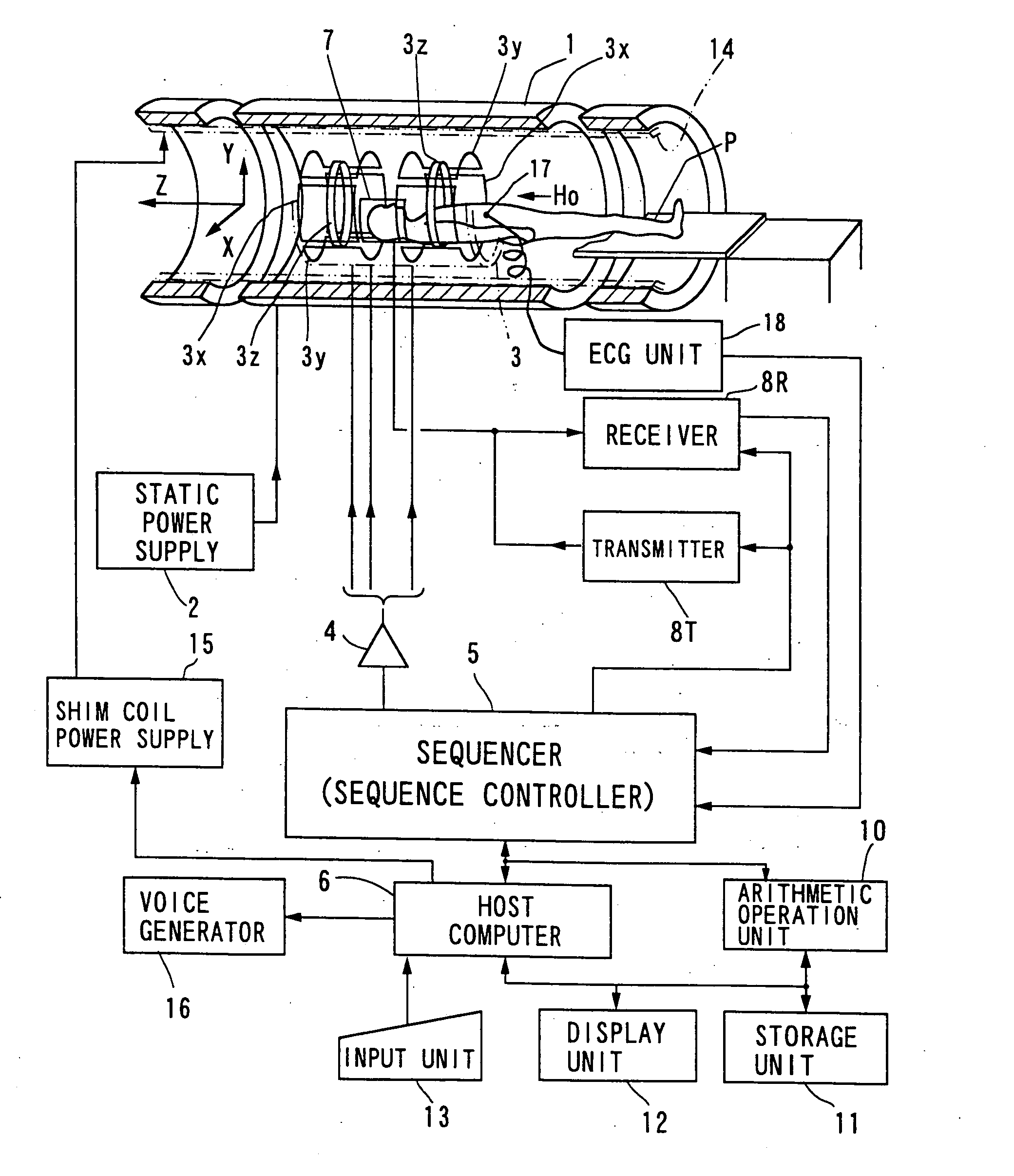
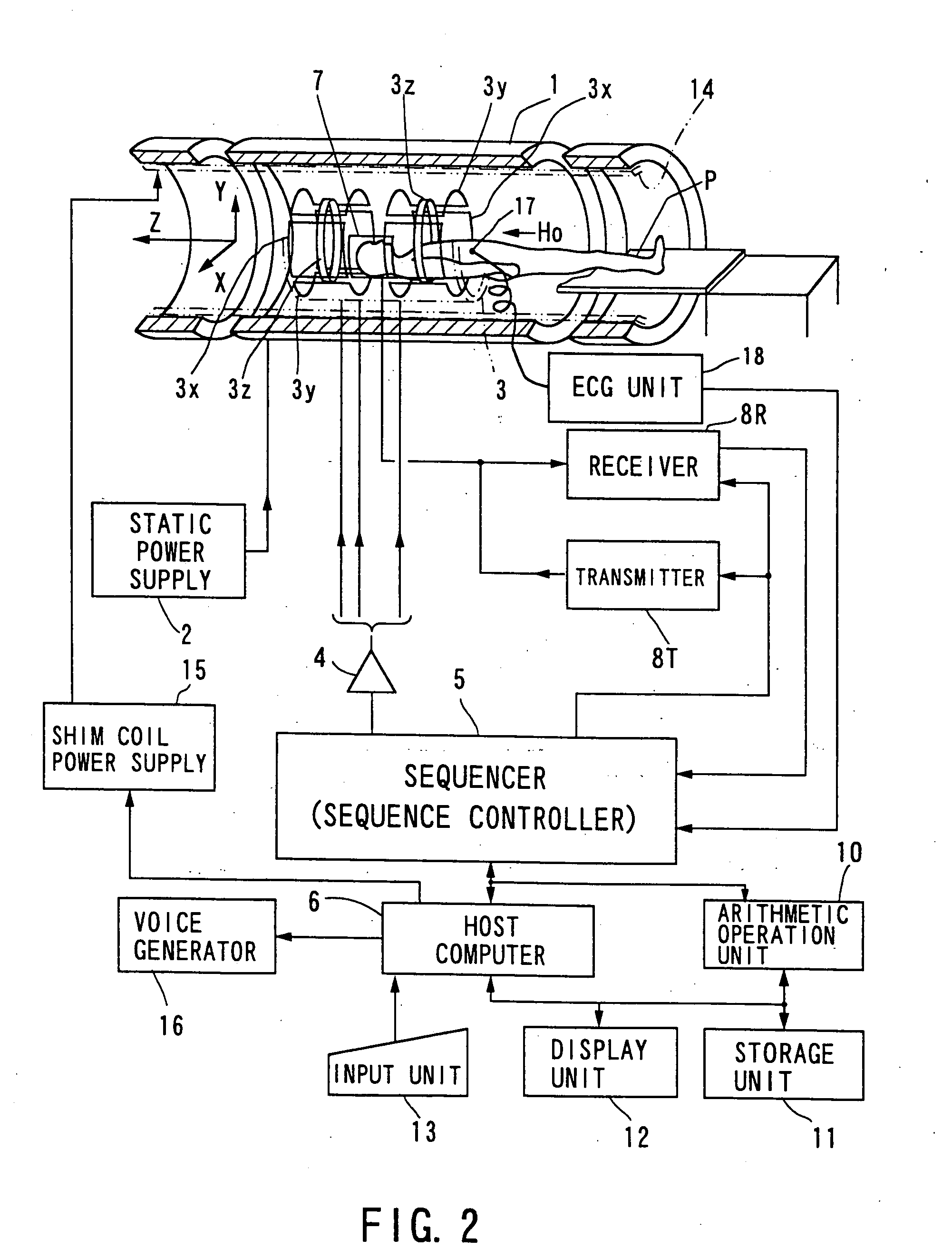
[0074]FIG. 2 shows the outlined configuration of a magnetic resonance imaging (MRI) system in accordance with the embodiment of the present invention, which will be described below.

[0075] The MRI system comprises a patient couch on which a patient P lies down, static magnetic field generating components for generating a static magnetic field, magnetic field gradient generating components for appending positional information to a static magnetic field, transmitting / receiving components for transmitting and receiving a radio-frequency (RF) signal, control and arithmetic operation components responsible for control of the whole system and for image reconstruction, electrocardiographing components for acquiring an ECG signal of a patient, which is a representative of signals indicative of cardiac temporal phases of the patient, and breath hold instructing components for instructing the patient to per...

second embodiment

[0141] Referring to FIGS. 10 to 17, a second embodiment of the present invention will be described.

[0142] In this embodiment, using a plurality of divided MT pulses described above, the parenchyma of the lungs of a patient will be imaged.

[0143] For MR-imaging the lungs, three approaches have been known primarily, which are to use a hyper-polarized gas (e.g. , xenon or helium), to perform a perfusion imaging using a contrast medium Gd-DTPA (refer to “Hatabu H, et al., MRM 36:503-508, 1996”), and to perform imaging with suction of oxygen using oxygen molecules (refer to “Edelman R R, et al., Nature Medicine 2, 11, 1236-1239, 1996).

[0144] Of these, the first approach is based on imaging at the MR frequency of, for example, a xenon gas (Xe) suctioned into the lungs. The second one is a technique to observe a perfused state of Gd-DTPA in blood. The third one utilizes a report that oxygen molecules, which are weakly paramagnetic, cause a signal from water to change sufficiently at the ...

third embodiment

[0189] Referring to FIGS. 18 to 20, a third embodiment of the present invention will be described.

[0190] The hardware construction of an MRI system of this embodiment is similar to those described in the foregoing embodiments.

[0191] The basic feature of the MRI system according to this embodiment is to use pulse sequences based on a single-shot (RF excitation) fast SE (spin echo) method on three-dimensional or two-dimensional slab (thick slice) scanning under ECG gating, in which MT (magnetization transfer) pulses of which flip angles and of which number are changeable are applied. The MT pulses are applied to give images MT contrasts based on MT effects fitted to imaging objects, and functions as means for produce an effective contrast between tissue and blood. Such pulse sequences are most effective in depicting the cardiac blood vessel systems. For instance, abdomen organs such as the heart can be imaged to provide T2-weighted contrast images. These images provides a tissue con...


PUM


Abstract

A magnetic resonance imaging (MRI) system includes an ECG detector for the patient object being imaged and an element for performing an MRI pulse sequence. An imaging unit defined by the pulse sequence is longer in temporal length than one heart beat represented by the ECG signal. An MR signal is acquired from the object in response to the pulse sequence and an MR image based on the acquired MR signal is produced. A plurality of divided MT pulses can be applied instead of the conventional single MT pulse. In this case, an SE-system pulse sequence having a shorter echo train spacing is used, to generate sounds by applying gradient pulses incorporated in an imaging pulse sequence so as to automatically instruct a patient to perform an intermittent breath hold during three-dimensional scanning.

Description

CROSS REFERENCE TO RELATED APPLICATIONS [0001] This application is a divisional of U.S. patent application Ser. No. 10 / 635,685 filed Aug. 7, 2003 which is a divisional of U.S. patent application Ser. No. 09 / 293,062 filed Apr. 16, 1999, now abandoned, and which claims priority from Japanese Application 108256 / 1998 filed Apr. 17, 1998 and Japanese Application No. 54614 / 1999 filed Mar. 2, 1999, the disclosure of which priority applications are incorporated herein by reference.BACKGROUND OF THE INVENTION [0002] 1. Field of the Invention [0003] The present invention relates to magnetic resonance imaging for imaging blood vessels and tissue of a subject (patient) on the basis of a magnetic resonance phenomenon occurring in the subject. More particularly, this invention is concerned with a magnetic resonance imaging (MRI) system and magnetic resonance (MR) imaging method that provides tissue / blood contrast images of a higher quality. [0004] In one aspect, such images are provided by utiliz...

Claims


Application Information

Patent Timeline
Patent Type & Authority Applications(United States)
IPC IPC(8): A61B5/055A61B5/352G01R33/563G01R33/567
CPCA61B5/0456A61B5/055A61B5/7207A61B5/7257A61B5/7285G01R33/5673G01R33/5605G01R33/5607G01R33/5615G01R33/5617G01R33/5635G01R33/4828A61B5/352
Inventor KASSAI, YOSHIMORIMIYAZAKI, MITSUESUGIURA, SATOSHI
Owner TOSHIBA MEDICAL SYST CORP
Why Eureka
Try Eureka