Needle alignment, needle securement and vessel stabilization device

a securement and vessel technology, applied in the direction of intravenous devices, catheters, needles infusion, etc., can solve the problems of significant trauma to the cannulatable vessel, large loss of blood, and irregular skin overlaying of cannulatable portions of the vessel

Inactive Publication Date: 2007-11-15
NXSTAGE MEDICAL
View PDF14 Cites 31 Cited by
  • Summary
  • Abstract
  • Description
  • Claims
  • Application Information

AI Technical Summary

Problems solved by technology

Particularly in the case of winged needle sets for hemodialysis and other extracorporeal procedures, a pair of winged needles must be placed in a very secure position on the surface of the skin, since the sharp cannula tips reside in the fistula or graft for a substantial period of time, and a great deal of blood could be lost if either needle de-cannulates from the patient, since a dialysis machine is pumping blood through the needles.
Additionally, significant trauma to the cannulated vessel occurs if the cannula is not maintained at an angle relative to the plane of the skin which prevents the sharp needle tip from touching or piercing the lateral or posterior wall of the cannulated fistula or graft.
Additionally, the skin overlaying such cannulatable portions of the vessel can be very irregular, resulting from the surgical procedure and growth of tissue surrounding such fistula or graft.
Another issue of arterial or fistulae/graft cannulation is that blood can spontaneously leak from around the cannulated needle at the cannulation site at any time during the 3-4 hour dialysis or other extracorporeal procedure, in which typically the patient is anticoagulated.
However, difficulties can arise with this and other taping styles for long dwell winged hub needle sets.
One difficulty is the inherent flexibility of all the principal components of the taping method: the wings and tubing themselves, the skin, and the tape.
Another difficulty results from movements during the tape application itself.
Such external movement is translated via a leverage point at the cannulation site into opposite movement of the sharp cannula tip within the vessel, often resulting in internal laceration of the vessel or even infiltration of the lateral or posterior vessel wall.
Another difficulty occurs when, typically, the back end of the winged hub is propped up off the skin surface by some millimeters, typically by the clinician's multi-folding of a piece of gauze to the desired thickness, in attempt to hold the external cannula/hub at a 15-30 degree angle for deeper vessels, with the clinician's goal of keeping the sharp cannula centrally located in the vessel during the entire procedure (i.e. away from the vessel walls).
However, the placement of this gauze often inadvertently urges the external cannula/hub upward, with the attendant movement of the internal, sharp needle tip downward, also risking infiltrati

Method used


Image

  • Needle alignment, needle securement and vessel stabilization device
  • Needle alignment, needle securement and vessel stabilization device
  • Needle alignment, needle securement and vessel stabilization device

Examples


third embodiment

[0048]FIG. 8 is a perspective view of this invention.

[0049]FIG. 9 is a plan view of the device of FIG. 8.

[0050]FIG. 10 is an elevational view of the device of FIGS. 8 and 9, shown resting on the skin, with the tape and winged needle removed.

[0051]FIG. 11 is a perspective view of another embodiment of this invention.

[0052]FIG. 12 is a side elevational view of FIG. 11.

DESCRIPTION OF SPECIFIC EMBODIMENTS

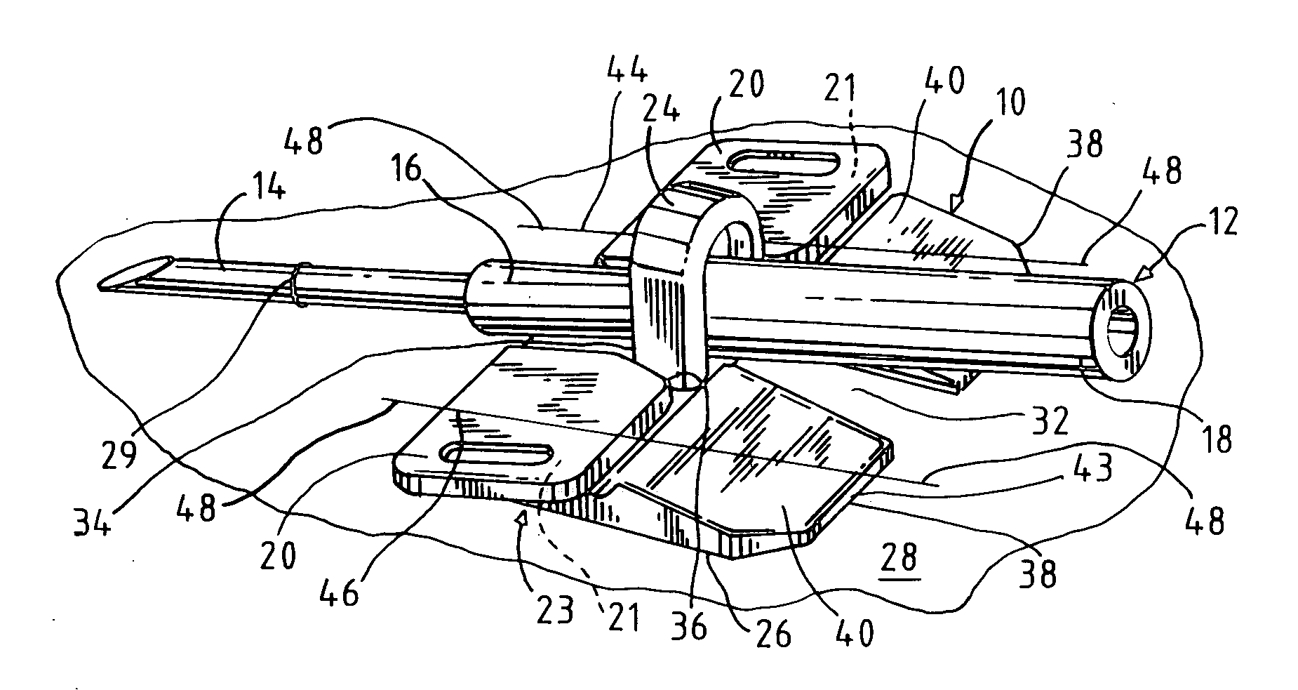
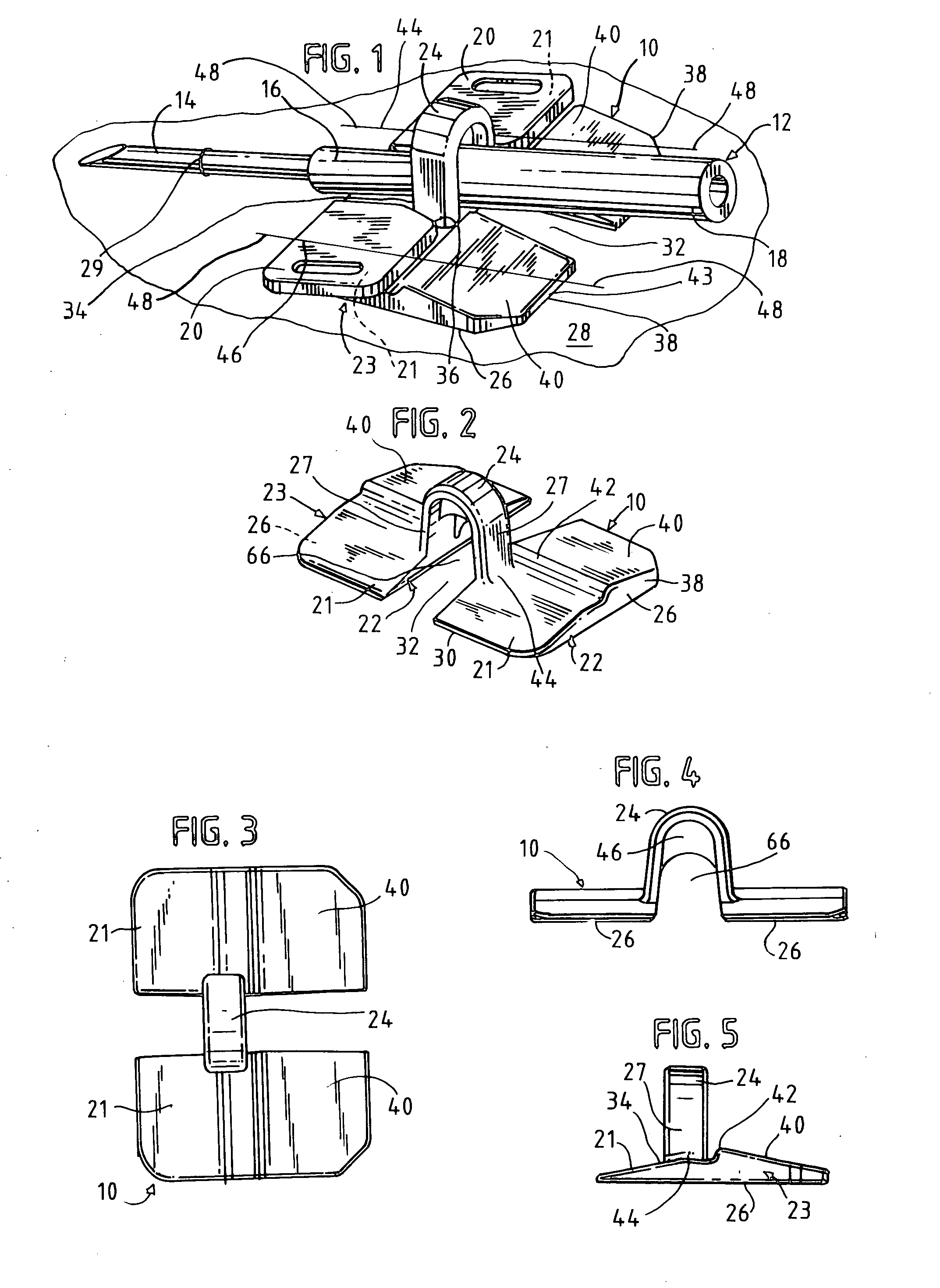
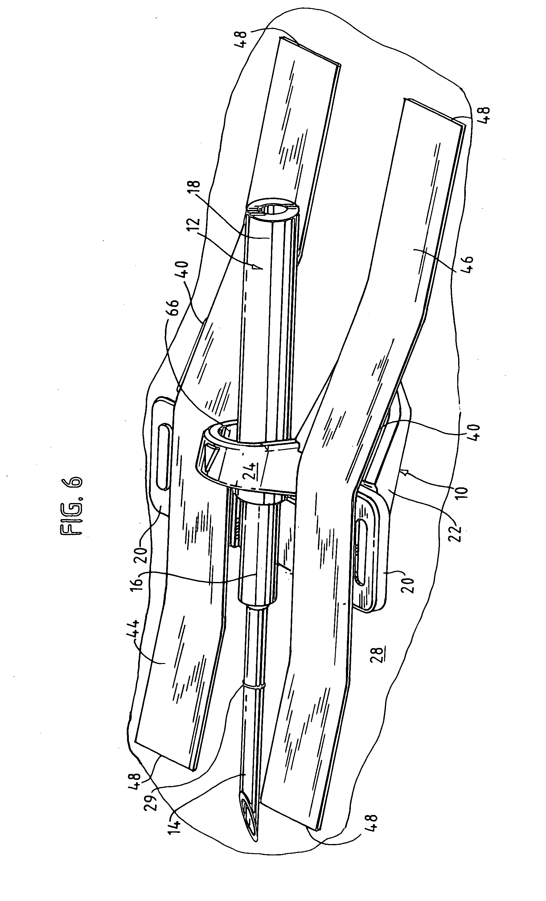
[0053] Referring to the drawings, FIGS. 1 and 2 show an alignment and securement device 10 which carries an intravenous, cannula 14 as part of a hemodialysis winged fistula needle set 12. Needle set 12 comprises cannula 14, needle hub 16 and flexible tubing 18, which typically terminates in a conventional tubing connector (not shown). Extending from hub 16 are a pair of flexible wings 20, of conventional design.

[0054] Wings 20 are shown to be resting at an alignment angle on a first, angled upper surface 21 of a forward portion 22 of base 23 of alignment and securement device 10. I...

first embodiment

[0068] Referring to FIGS. 8-10, another embodiment of securement device 60 is disclosed. Securement device 60 defines a bifurcated base 23b, comprising two separate segments as shown, similar to base 23 of the As before, an inverted U-shaped, self-supporting strap 24b is provided, connecting the separate base segments 23b. Specifically, the embodiment of FIGS. 8-10 is similar to the embodiment of FIGS. 1-6, except as otherwise described herein.

[0069] Base segments 23b each define a first optionally angled upper surface 21b, and also a second optionally angled upper surface 40b, the surface angles being opposed to each other, and the same or different relative to bottom surface 67 and to the skin 64 when flat and placed thereon. As shown a central portion of bottom of surface 67 is spaced from the skin 64, while end portions 76, 78 are in contact with the skin. A plastic-saving recess 62 may optionally be placed on the underside of base segments 23b so that the flat bottom 67 is rai...


PUM


Abstract

A securement device for an intravenous, winged needle set, which comprises: an inverted U-shaped, self-supporting strap, the strap having vertical legs attached to a central portion of a base. The base has a bottom to rest on the skin of the patient. A portion of the base forward of the strap has an upper surface that slopes downwardly to a forward end at an angle to the skin and the bottom of the base. Improved retention and ease of application is provided with such a device.

Description

BACKGROUND OF THE INVENTION [0001] Hollow bore cannulae of a needle set for access to the vascular system of a patient have sharp tips at their distal end which are cannulated through the skin and vessel wall, and such tips reside within the vessel lumen. Often, as is well known, winged hub needle sets are used, one advantage of the wings being that they aid in the practitioner's secure and rigid holding of the device during cannulation, and then because of their flexibility may be flattened onto the skin and provide a taping aid to tape the device in place on the skin. [0002] Particularly in the case of winged needle sets for hemodialysis and other extracorporeal procedures, a pair of winged needles must be placed in a very secure position on the surface of the skin, since the sharp cannula tips reside in the fistula or graft for a substantial period of time, and a great deal of blood could be lost if either needle de-cannulates from the patient, since a dialysis machine is pumping...

Claims


Application Information

Patent Timeline
IPC IPC(8): A61M5/32
CPCA61M25/02A61M25/0612A61M2025/0293A61M2025/0266A61M2025/0253
Inventor UTTERBERG, DAVIDBELL, DAVIDSCHNELL, WILLIAM J.
Owner NXSTAGE MEDICAL
Why Eureka
Try Eureka