Shock Isolation System for an Inertial Sensor Array

a technology of inertial sensor and isolation system, which is applied in the direction of speed measurement using gyroscopic effects, damping movement measurement devices, and devices characerised by mechanical means, etc. it can solve problems such as especially serious problems for engineers, and achieve the effects of improving the measurement accuracy of inertial sensor arrangement, shock, impact and vibration isolation, and low weigh

Active Publication Date: 2007-11-22
PRUTECHNIK DIETER BUSCH AG
View PDF11 Cites 4 Cited by
  • Summary
  • Abstract
  • Description
  • Claims
  • Application Information

AI Technical Summary

Benefits of technology

[0006] The object of the invention is to devise improved shock, impact and vibration isolation for an inertial sensor arrangement which is continually active, which distinctly improves the measurement ...

Problems solved by technology

Making available a shock isolation system for inertial sensor arrangements, especially those with optically opera...

Method used


Image

  • Shock Isolation System for an Inertial Sensor Array
  • Shock Isolation System for an Inertial Sensor Array
  • Shock Isolation System for an Inertial Sensor Array

Examples


Embodiment Construction

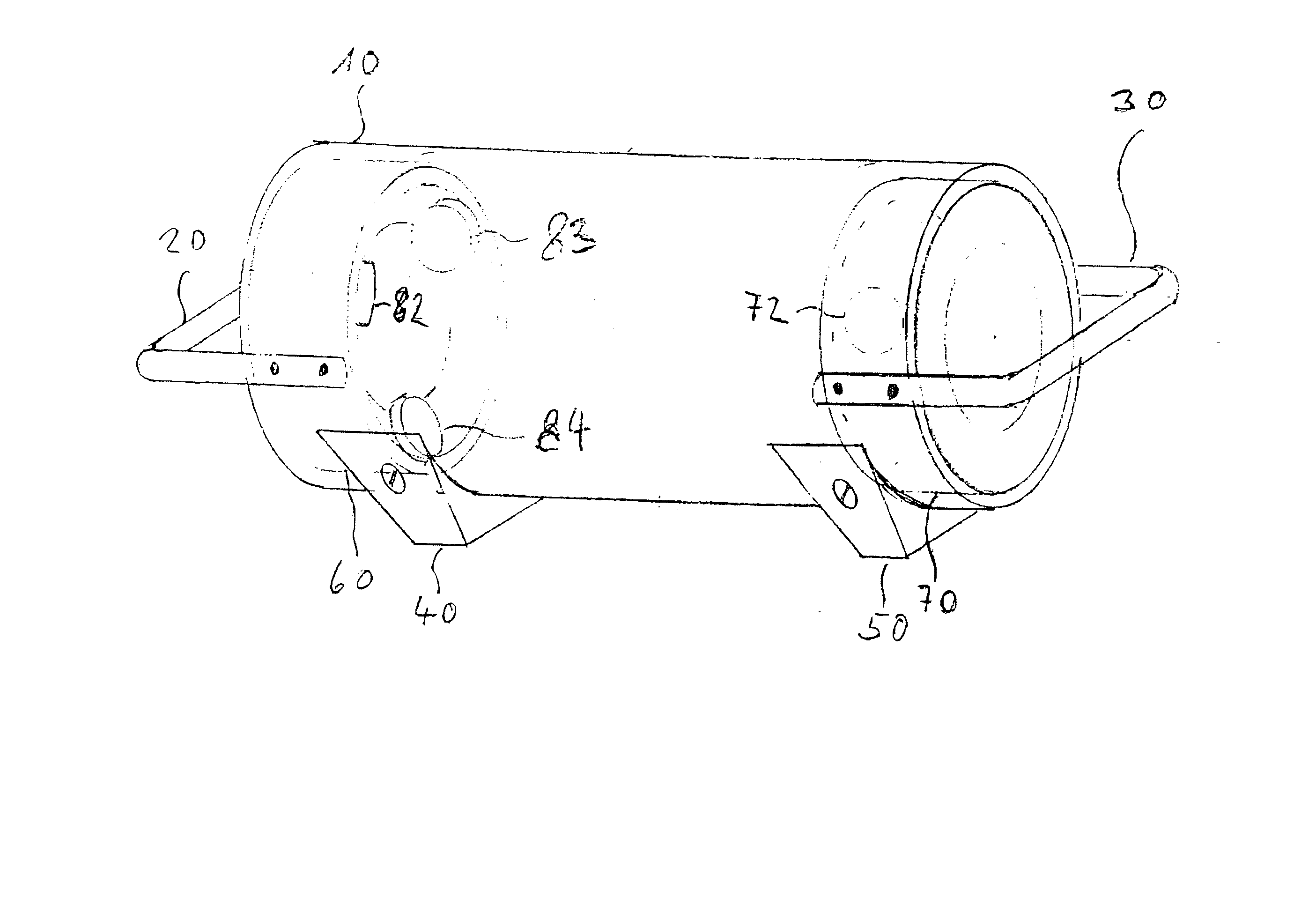
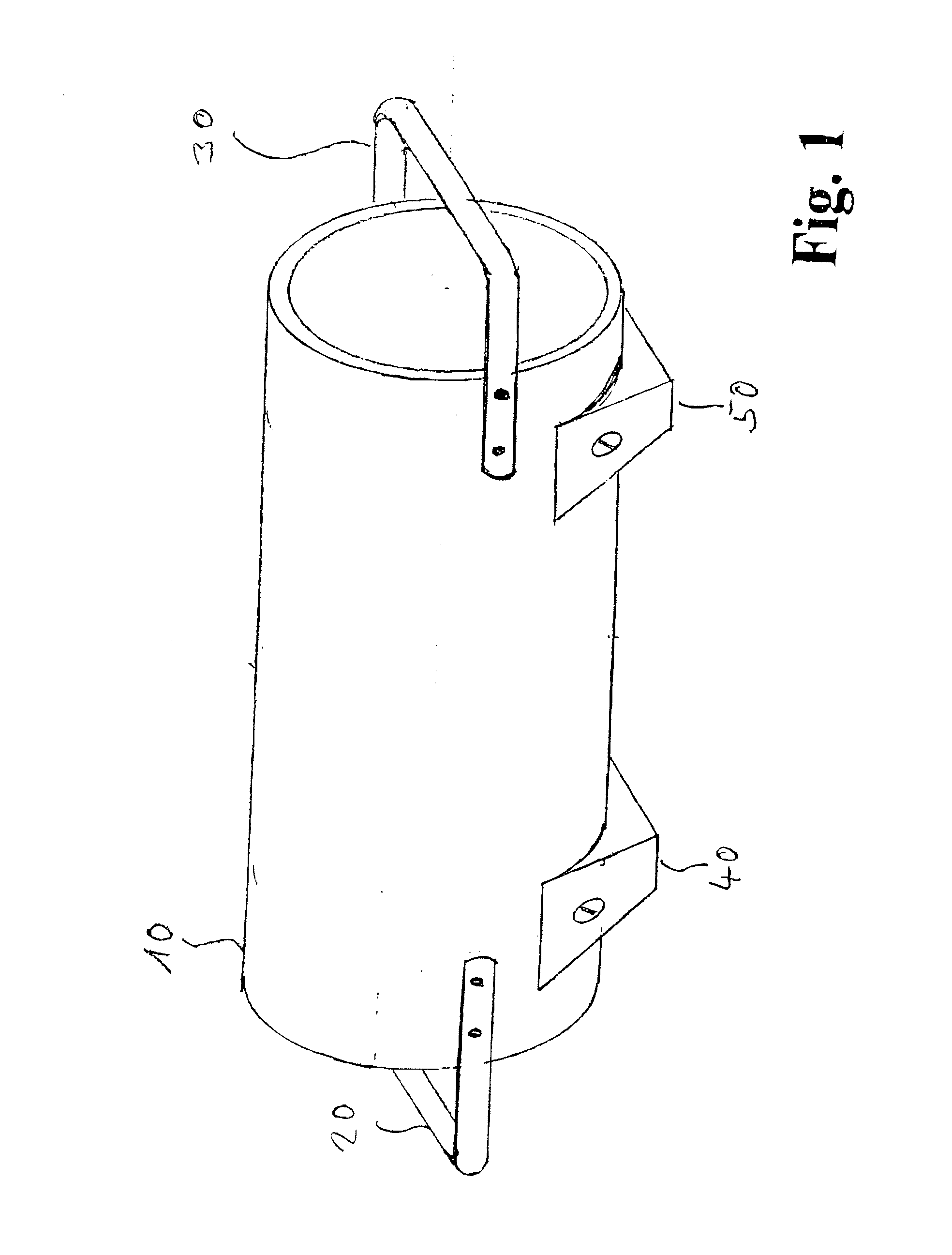
[0020]FIG. 1 shows, in a outside view, the general shape of the inertial probe in accordance with the invention. It has an essentially cylindrical shape; this is due to a cylindrical outside jacket 10. Carrying handles 20, 30 are attached to it. With these carrying handles, the inertial probe can be seated by means of skids 40, 50 on the articles to be measured, or can be pivoted on cylindrical objects according to the teaching of German Patent Application DE 101 94459.4 and corresponding U.S. Pat. No. 6,591,218, which is incorporated by reference to the extent necessary to complete an understanding of this aspect of the invention. Using the cylindrical outside jacket 10 yields an economical arrangement which is characterized by especially high mechanical stability.

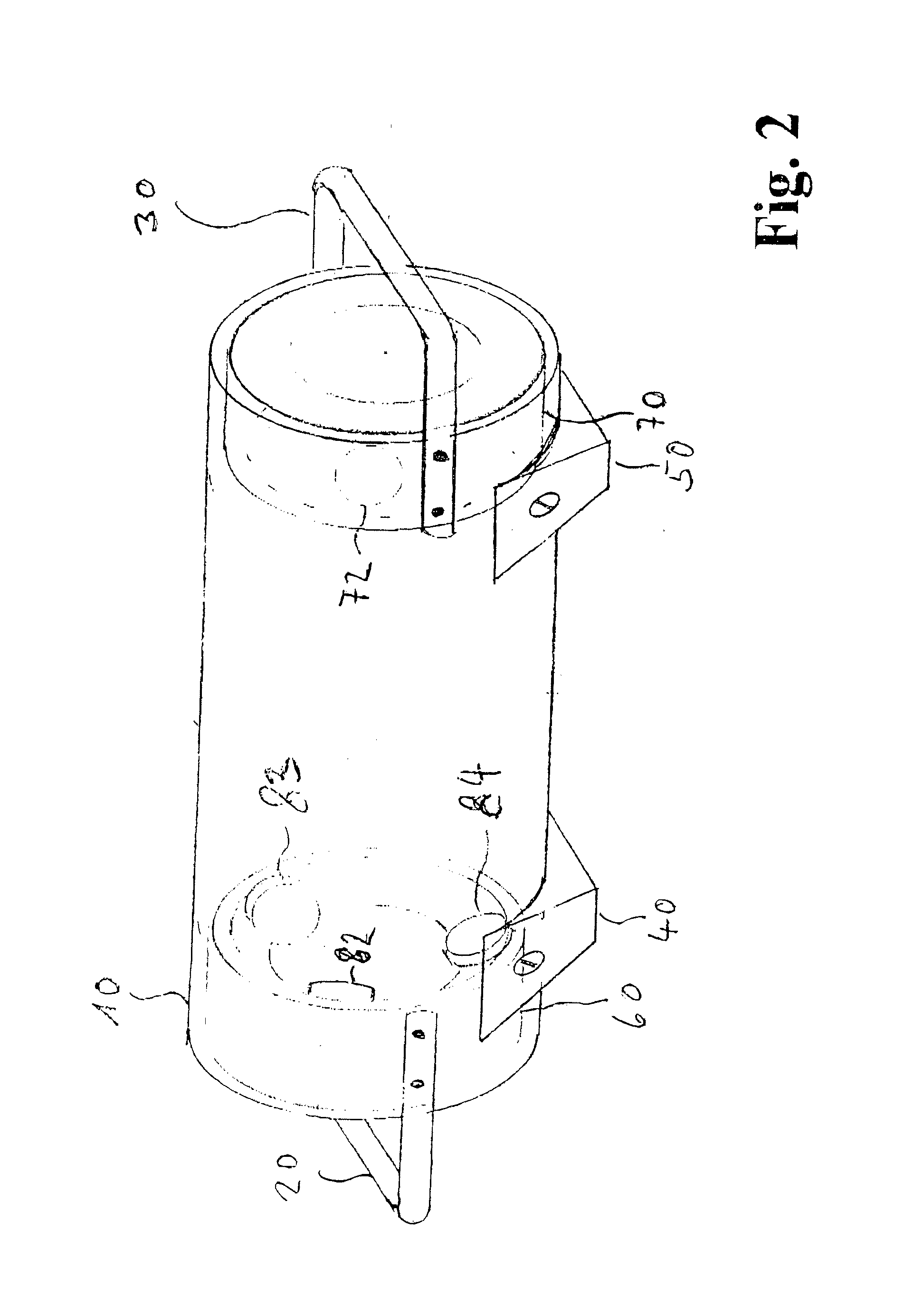
[0021] As FIG. 2 shows, a set of shock reducing supports 60, 70 is provided in a concentric arrangement within the cylindrical outside jacket 10. A number of shock mounts 82, 83, 84, 85 etc. are attached to them precisel...


PUM


Abstract

The shock isolation system for an inertial sensor arrangement, on the one hand, causes an advantageous moment of inertia by the special arrangement of the individual sensors, especially of the gyroscope used. On the other hand, an advantageous long interval of the required shock-absorbing components (“shock mounts”) is provided by the use of several tubular shells. A measurement device with this inertial sensor arrangement thus achieves improved accuracy and reliability.

Description

BACKGROUND OF THE INVENTION [0001] 1. Field of the Invention [0002] This invention relates to a shock isolation system for an inertial sensor arrangement. [0003] 2. Description of Related Art [0004] A system for isolation or damping of vibrations acting on an inertial sensor arrangement is known from U.S. Pat. No. 5,890,569 (inventor—Goepfert). [0005] Making available a shock isolation system for inertial sensor arrangements, especially those with optically operating gyroscope systems, or highly sensitive accelerometers, always poses an especially serious problem for the engineer. On the one hand, long enough spring paths must be prepared to reliably capture impacts or mechanical shock effects, on the other hand, the relative position of the inertial sensor arrangement to be protected or isolated in relation to the measurement surfaces or edges to be defined may not be significantly changed by the effect of temperature or its position changes within the framework of measurement accu...

Claims


Application Information

Patent Timeline
IPC IPC(8): G01C19/66G01P1/02H02G3/06
CPCF16F15/02G01P1/023F16F15/04
Inventor LYSEN, HEINRICH
Owner PRUTECHNIK DIETER BUSCH AG
Why Eureka
Try Eureka