Welding machine

A technology for welding machines and welding racks, which is applied in welding accessories, welding protection devices, mechanical equipment, etc. It can solve problems such as solder easily adhering to the welding rack, uneven welded parts, and affecting the quality of welded parts, so as to protect the body Effects of health, increased vibration, and improved welding efficiency

Pending Publication Date: 2021-03-12
何亚成
View PDF9 Cites 0 Cited by
  • Summary
  • Abstract
  • Description
  • Claims
  • Application Information

AI Technical Summary

Problems solved by technology

[0006] Aiming at the deficiencies of the prior art, the present invention provides a welding machine, which solves the problem of evaporation, condensation and gas generation of welding rods, welding parts and coatings under the high temperature of the arc during the welding process, resulting in a large number of smoke particles and arc light radiation at the same time. Under the strong radiation of the arc, the air around the arc produces toxic gas, and the melted solder is easy to adhere to the welding frame, causing uneven welding parts and affecting the quality of welding parts.

Method used


Image

  • Welding machine
  • Welding machine
  • Welding machine

Examples


Embodiment 1

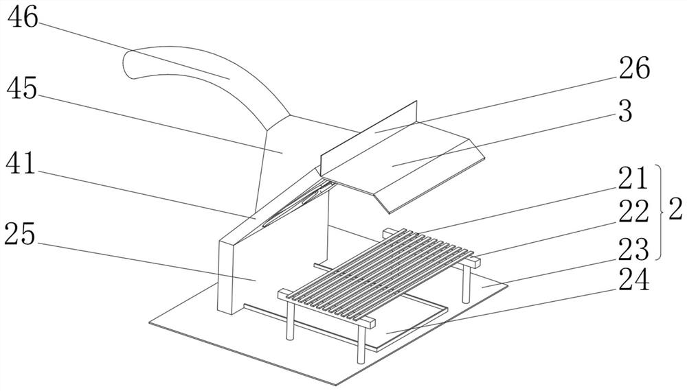
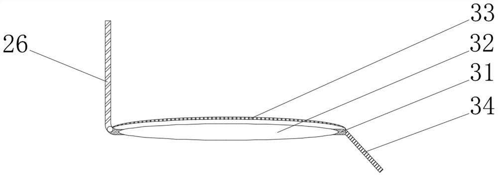
[0041] See Figure 1-2 The present invention provides a technical solution: a welding machine, a welding body 1 comprising a welding frame 2, a protective mechanism 3, and a diaaching mechanism 4, and the welding frame 2 includes a slider 21, a bottom fixed connection of the slider 21. The support frame 22, the bottom of the support frame 22 is fixedly connected to the base 23, and the top sliding of the base 23 is slidably connected to the scrap cartridge 24, and the top of the base 23 is fixedly connected to the waste passage 25, the top of the waste passage 25 fixes the connection. Institution 4, the top of the right side of the vacuum cleaner 4 fixedly connected to the receiving plate 26, and the bottom right side of the underside plate 26 is rotated by the damper shaft, the left side of the waste cassette 24 penetrates the waste passage 25 and extended to the waste The outside of the pass plate 25, the bottom of the waste passage 25 is connected to each other with the inside ...

Embodiment 2

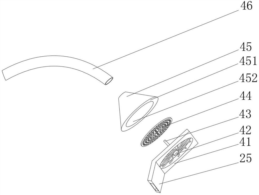
[0045] See Figure 1-5 Based on the first example, the present invention provides a technical solution: the diaaching mechanism 4 includes a vacuum-saving frame 41, and the inside of the vacuum cleaning frame 41 is fixedly connected to the microscope 42, and the left side fixed connection of the micro motor 42 is The receiving rod 43, the inner receptor 43 is fixed to one end of the micro motor 42 is fixedly coupled with the filter 44, and the top of the left side of the vacuum frame 41 is fixedly connected to a kit 45, and the top of the sleeve 45 has a vacuum tube 46, a filter The outer side of 44 is fixed to the right side wall of the sleeve frame 45, and the bottom end of the vacuum cleaner 41 is in communication with the top right side of the scrapper plate 25, and the top end of the waste passage 25 penetrates the dust frame 41 and extends to the kit 45. internal.

[0046] The first suction hole 451 and the second suction hole 452 are provided inside the sleeve 45.

[0047] ...

Embodiment 3

[0051] See Figure 1-8 On the basis of the first and embodiment 2, the present invention provides a technical solution: the outer sleeve of the slider 21 is provided with a slag-slag-slag, the inside of the slag mechanism B is slidable, divided by the outside of the slider 21, divided The left side of the slag mechanism B is fixedly connected to the hydraulic telescoping rod 211, and the outer side of the hydraulic telescopic rod 211 is fixed to the left side of the slider 21.

[0052] The slag mechanism B includes a slag frame B1, and the inner wall of the slag frame B1 is fixedly connected to the first electromagnetic block B2, and both sides of the first electromagnetic block B2 are fixedly connected to the active rod B3, and the bottom fixed connection of the movable rod B3 is slippery. The top of the knife B4, the top of the slipper B4 is fixedly connected to the second electromagnetic block B5, and the second electromagnetic block B5 is located directly below the first electr...


PUM


Abstract

The invention discloses a welding machine which comprises a welding body composed of a welding rack, a protection mechanism and a dust suction mechanism, the welding rack comprises a sliding rod, a supporting frame is fixedly connected to the bottom of the sliding rod, a base is fixedly connected to the bottom of the supporting frame, a waste box is slidably connected to the top of the base, a waste through plate is fixedly connected to the top of the base, the dust suction mechanism is fixedly connected to the top end of the waste through plate, and a bearing plate is fixedly connected to thetop of the right side of the dust suction mechanism. The welding machine relates to the technical field of welding. The welding machine solves the problems that in the welding process, a welding rod,a weldment and a coating generate evaporation, condensation and gas under the high-temperature effect of electric arcs, a large number of smoke particles are generated, meanwhile, eyes and skin of people are radiated by arc light, air around the electric arcs generates toxic gas under the intense radiation effect of the arc light, meanwhile, molten welding flux is prone to adhering to the weldingrack, as a result, the quality of the weldment is affected due to unevenness of the weldment.

Description

Technical field [0001] The present invention relates to the field of welding technology, and is specifically a welder. Background technique [0002] By heating or pressurizing or both, and using or without filling material, the welding is called welding, but welding can not only solve the connection of various steel, but also solve aluminum, copper and other non-ferrous metals and The connection of special metal materials such as titanium and zirconia has been widely used in mechanical manufacturing, shipbuilding, marine development, automobile manufacturing, petrochemical, aerospace technology, atomic energy, electricity, electronic technology and construction. According to the statistics of industrial developed countries, steel materials used after welding processing are required to account for about 45% of the total steel production of steel. [0003] According to Chinese Patent CN105799152A, a welding machine involves the technical field of automotive parts processing technol...

Claims


Application Information

Patent Timeline
Patent Type & Authority Applications(China)
IPC IPC(8): B23K9/32F16P1/06
CPCB23K9/32B23K9/322F16P1/06
Inventor 何亚成
Owner 何亚成
Why Eureka
Try Eureka