
Ellipsometer and Ellipsometry

a technology of optical polarization analysis and ellipsometry, which is applied in the direction of optical radiation measurement, polarising elements, instruments, etc., can solve the problem of limited wavelength bandwidth of near-infrared, and achieve the effect of high reliability

Inactive Publication Date: 2007-11-22
PHOTONIC LATTICE +1
View PDF5 Cites 20 Cited by
  • Summary
  • Abstract
  • Description
  • Claims
  • Application Information

AI Technical Summary

Benefits of technology

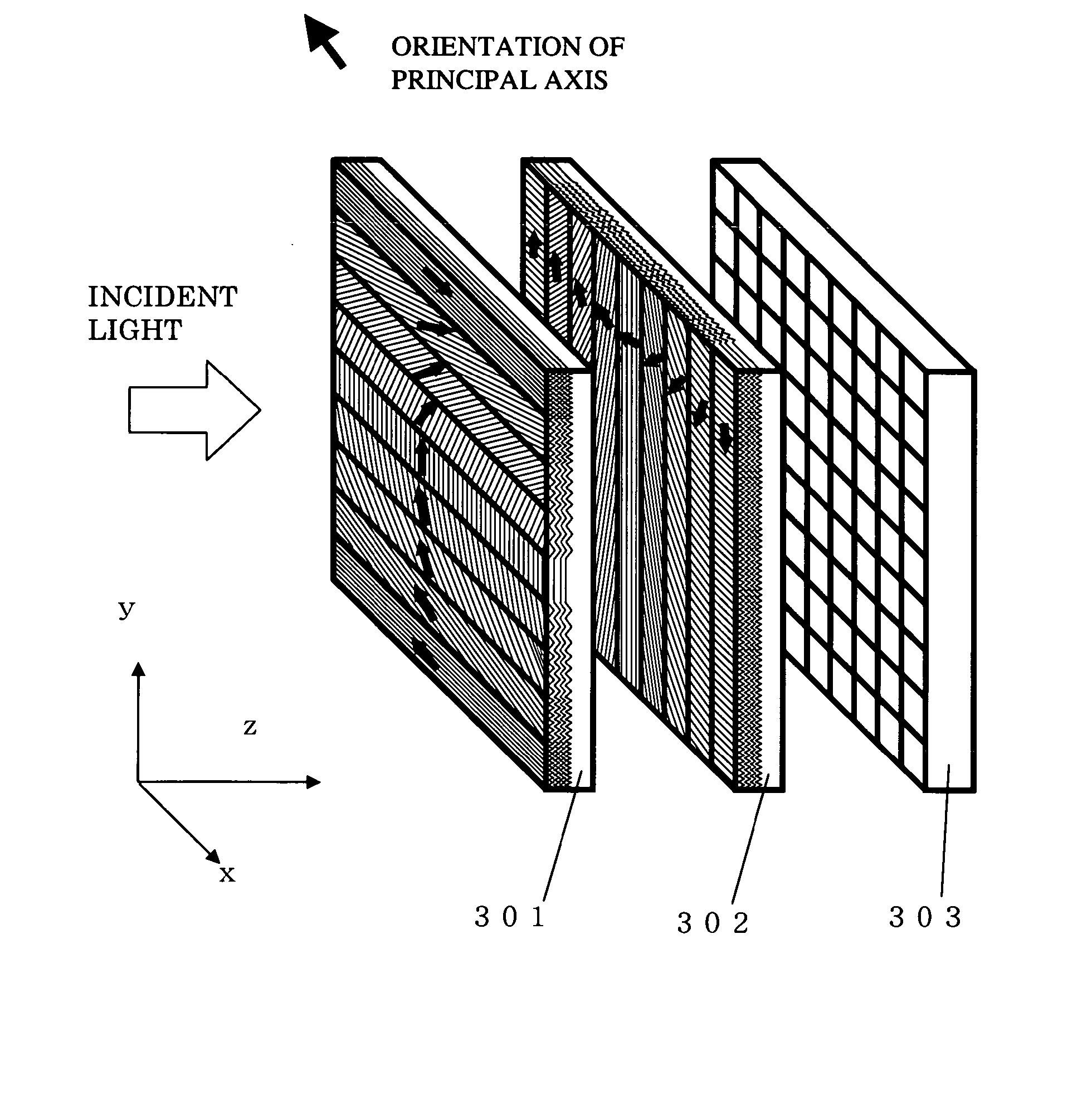
[0007] The present invention provides a driverless polarization analysis device or ellipsometer that is constituted by integrating a polarizer array having a plurality of regions with mutually different optical axis directions, a wavelength plate array having a plurality of regions with mutually different optical axis directions or retardations (phase differences), and a light-receiving element array, as well as a polarization analysis method that employs the driverless polarization analysis device or ellipsometer. By adopting an artificial optical material that comprises a multidimensional cyclic structure known as a photonic crystal as the polarizer array and wavelength plate array, a highly reliable device that is sufficiently small can be implemented.

Problems solved by technology

However, the useful wavelength bandwidth is limited to near-infrared.

Method used


Image

  • Ellipsometer and Ellipsometry
  • Ellipsometer and Ellipsometry
  • Ellipsometer and Ellipsometry

Examples


example 1

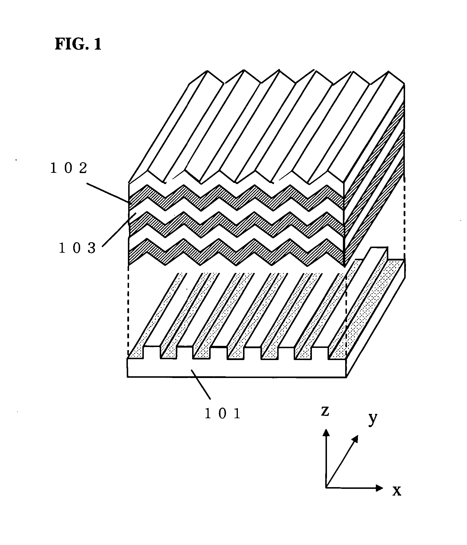
[0105] An example in which the wavelength plate array and polarizer array in the polarization analysis device of claims 1 to 6 are integrated is shown in FIG. 20. A polarizer array is created by forming a groove pattern on the substrate 2004 and depositing a multilayered film 2003 on the groove pattern of substrate 2004. A termination layer 2002 of the polarizer array layer is deposited quite thickly and, when sputter etching is performed strongly at the same time, the corrugated shape formed by autocloning is eliminated and a level surface is completed. There is no particular problem even when mechanical grinding is used to smooth the surface. Thereafter, a wavelength plate array is created by newly forming a wavelength plate line and space pattern by means of lithography and depositing a multilayered film 2001 by means of autocloning. For alignment of the patterns of the polarizer array and wavelength plate array, alignment markers may be placed on a portion of the substrate befor...

example 2

[0106]FIG. 21 shows another example that integrates the wavelength plate array and polarizer array of the polarization analysis device of claims 1 to 6. In this case, integration can be implemented by forming a groove pattern on the upper and rear sides of a substrate 2102 and forming a wavelength plate array layer 2101 and a polarizer array layer 2103 by means of autocloning. For pattern alignment, a transparent substrate such as SiO2 may be used for the substrate 2102 and alignment markers may be added to the substrate. A small polarization analysis device can be implemented by combining the integrated wavelength plate / polarizer array with a light-receiving element array 2104.

example 3

[0107] Although also clear from FIGS. 4 and 7, the position of zero intensity appears as a line rather than a spot when a certain specified polarized wave enters either a wavelength plate angle variation-type polarization analysis device or a wavelength plate phase difference variation-type polarization analysis device. For example, in the case of an angle variation-type polarization analysis device (FIG. 4), when clockwise or counterclockwise circularly polarized light enters the polarization analysis device, in the case of a phase difference variation-type polarization analysis device (FIG. 7), and when linearly polarized light of the same direction as the principal axis angle of the wavelength plate or of a direction orthogonal to the direction of the principal axis angle enters the polarization analysis device, the intensity distribution is linear. When dark spot detection is adopted as the polarization analysis algorithm, the bottom position (or peak position) of these singular...


PUM


Abstract

A small and high-speed polarization analysis device and ellipsometer having no driving section are provided by overlapping one polarizer array rendered by arranging a plurality of polarizer regions of mutually different optical axis directions in the form of stripes and one wavelength plate array rendered by arranging a plurality of wavelength plate regions of fixed retardation and mutually different optical axis directions in the form of stripes so that the respective stripes of the plurality of polarizer regions and of the plurality of wavelength plate regions intersect one another and by disposing a light-receiving element array so that the intensities of light that has passed through the matrix-like intersection parts can be individually measured. As a method of analyzing a two-dimensional intensity distribution pattern that is observed by the light-receiving element array of the polarization analysis device, either one of (or both of) the algorithms of a method that determines incident polarized waves by mathematically fitting pattern shapes or performing database matching or a method that performs a Fourier transform on pattern shapes and determines incident polarized waves from the frequency components is (are) used. Furthermore, if necessary, more accurate polarization analysis is also possible by adopting a signal processing method that removes signals from light-receiving element regions that receive unnecessary scattered light and diffracted light.

Description

TECHNICAL FIELD [0001] The present invention relates to an optical polarization analysis device and an ellipsometer that measures the optical constant and thickness of a thin film by using the optical polarization analysis device. BACKGROUND ART [0002] Representative methods for analyzing the film quality and film thickness of a thin film include ellipsometry, which is a known old procedure. Ellipsometry is a procedure that inputs light in a specified polarization state to a thin-film sample and determines the film thickness and the refractive index of a sample and so forth by measuring the ratio ρ between the reflectance Rp of a component (p polarized wave) whose electric field is parallel to the incident face and the reflectance Rs of a component (s polarized wave) whose electric field is perpendicular to the incident face, in the light that is reflected by the sample. Here, ρ is generally a complex number and can be expressed as ρ=Rp / Rs=tan(ψ)×exp(jΔ). ψ and Δ are parameters that...

Claims


Application Information

Patent Timeline
IPC IPC(8): G01J4/00G02B5/30G06F19/00G01J4/04G01N21/21
CPCG01N21/211G01J4/04
Inventor KAWAKAMI, SHOJIROSATO, TAKASHIHASHIMOTO, NAOKISASAKI, YOSHIHIRO
Owner PHOTONIC LATTICE
Learn More