
Intramedullary transillumination apparatus, surgical kit and method for accurate placement of locking screws in long bone intramedullary rodding

a technology of intramedullary rodding and intramedullary rodding, which is applied in the field of intramedullary transillumination apparatus, surgical kit and method for accurate placement of locking screws in long bone intramedullary rodding, can solve the problems of not commercially developed techniques and apparatus of the abovementioned elstrom et al. patents, and the difficulty of aligning the drill based on the light or infrared energy tha

Inactive Publication Date: 2007-11-22
GURTOWSKI JAMES P
View PDF3 Cites 26 Cited by
  • Summary
  • Abstract
  • Description
  • Claims
  • Application Information

AI Technical Summary

Benefits of technology

[0012]It is a first object of the present invention to provide apparatus and surgical instruments to improve the accuracy and precision of drilling holes in bones for locking screws for intramedullary nails.
[0014]It is a further object of the invention to provide this technique minimizing radiation exposure to the patient and operative staff.
[0017]It is yet another object of the invention to provide a method and apparatus which facilitate treatment of long bone fractures under less than ideal treatment facilities, such as military field hospitals, or when reliable x-ray equipment may not be available.
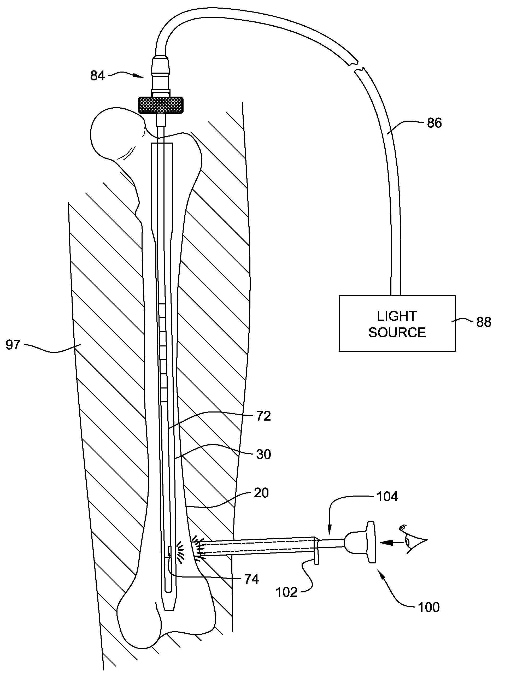
[0027]Thus, the invention is directed to an apparatus, for use (by a surgeon or surgical robot) with a surgical drill in the repair of bones using an intramedullary nail insertable into a patient's bone, the intramedullary nail having a hollow body portion and a distal transverse hole. The apparatus comprises in combination a rod like device for insertion into the intramedullary nail, the device having a light source emitting electromagnetic non-ionizing radiation in the infrared or visible portions of the electromagnetic spectrum, and the device being positionable so that the light source emits the radiation through the distal transverse hole of the intramedullary nail; and a surgical instrument for exposing an exterior surface of a portion of the bone illuminated by the radiation for view by the surgeon; whereby visual detection of the radiation on the exterior surface of the bone (directly by the surgeon or by a camera) and alignment of the surgical drill to the radiation passing through the transverse hole of the intramedullary nail aligns the surgical drill with the transverse hole, permitting accurate drilling of a hole through the bone and passage of the drill through the transverse hole of the intramedullary nail.
[0031]The surgical instrument may comprise a scalpel for making an incision in tissues of the patient to permit the surgeon to directly view the exterior surface of a portion of the bone illuminated by the radiation. The surgical instrument may further comprise a retractor for retracting the tissues of the patient on at least one side of the incision, to assist the surgeon in obtaining the direct view of the exterior surface of a portion of the bone illuminated by the radiation.
[0033]The light source may comprise a laser. The apparatus may comprise a shaping mask for the light source for providing a shape to a beam of radiation from the device, to assist in precisely locating a center of the beam.

Problems solved by technology

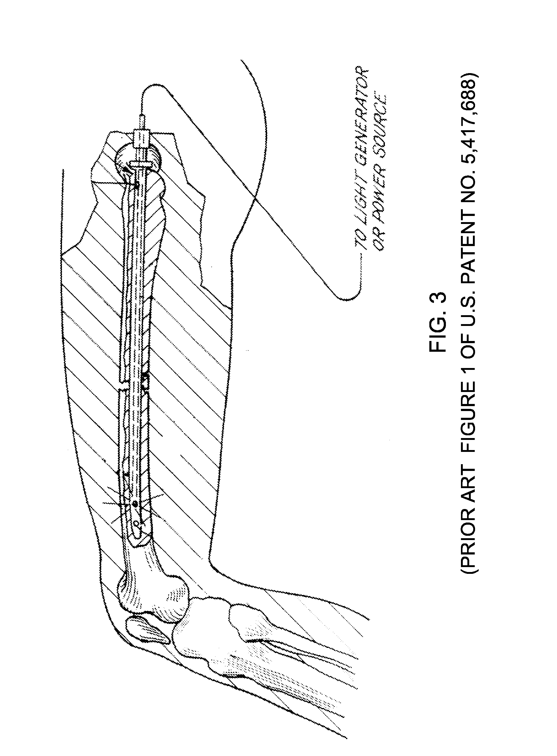
As far as is known, the techniques and apparatus of the abovementioned Elstrom et al. patents have not been commercially developed.
One possible reason for this may be that while the concept is sound, there are practical difficulties in aligning the drill based on the light or infrared energy that reaches the surface or skin of the patient.
While this may not pose serious difficulties in the case of portions of bones located very close to the surface of the skin (especially if the patient does not carry excess tissues due to obesity), in many cases, the travel through the patient's tissues, from the bone to the skin, tends to diffuse the energy, (which is a well defined circle on the surface of the bone) into an ill defined illuminated region, which, in some cases, and in some patients, is of relatively little assistance in providing guidance to the surgeon in the placement of locking screws.

Method used


Image

  • Intramedullary transillumination apparatus, surgical kit and method for accurate placement of locking screws in long bone intramedullary rodding
  • Intramedullary transillumination apparatus, surgical kit and method for accurate placement of locking screws in long bone intramedullary rodding
  • Intramedullary transillumination apparatus, surgical kit and method for accurate placement of locking screws in long bone intramedullary rodding

Examples


Embodiment Construction

[0053]Reference is made to FIG. 5 for a cross-sectional view, and to FIG. 7, for a plan view of an apparatus 70 incorporating features of the present invention. Although the present invention will be described with reference to the embodiments shown in the drawings, it should be understood that the present invention can be embodied in many alternate forms of embodiments. In addition, any suitable size, shape or type of elements or materials could be used.

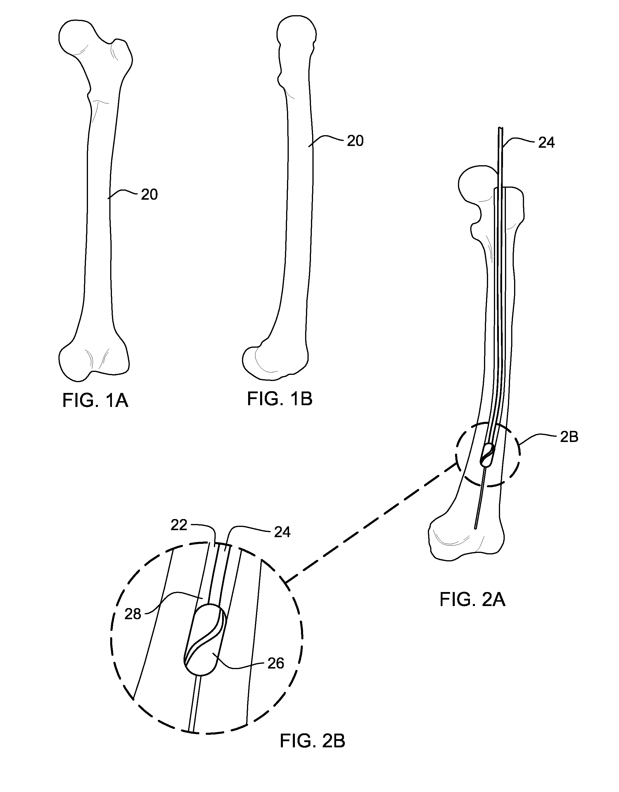
[0054]The apparatus 70 comprises a suitable light conduction device or member 72 for insertion into intrameduallary rod 30, generally after intrameduallary rod 30 is positioned in canal 28 of the bone 20 or other bone. Member 72 is designed to be somewhat flexible, and has a diameter permitting relatively easy insertion into intrameduallary rod 30. Thus, members 72 may be produced in several different outer diameters including but not limited to 2 mm, 2.5 mm, 3 mm, 3.5 mm 4 mm, 4.5 mm as necessary to correspond to existing cannulati...


PUM


Abstract

Apparatus, including a surgical kit, for use with a surgical drill, in the repair of bones using an intramedullary nail insertable into a patient's bone, comprising a rod like device for insertion into the intramedullary nail, the device having a light source emitting electromagnetic non-ionizing radiation in the infrared or visible portions of the electromagnetic spectrum, and the device being positionable so that the light source emits the radiation through a distal transverse hole of the intramedullary nail; and a surgical instrument for exposing an exterior surface of a portion of the bone illuminated by the radiation for view by the surgeon. The surgeon can detect the radiation on the exterior surface of the bone and align the surgical drill to the radiation passing through the transverse hole of the intramedullary nail, permitting accurate drilling of a hole through the bone and passage of the drill through the transverse hole of the intramedullary nail.

Description

[0001]This application claims priority, under 35 U.S.C. §119(e), from provisional patent application Ser. No. 60 / 797,986 filed on May 5, 2006, which is hereby incorporated herein, by reference, in its entirety.BACKGROUND OF THE INVENTION[0002]1. Field of the Invention[0003]The present invention relates to the apparatus, methods, technique and accuracy of the placement of distal locking screws during the procedure of long bone intramedullary nailing (also known as: intramedullary rodding and for the purposes of this description will be used synonomously). More particularly, it relates to those apparatus, methods and systems for accurate placement of distal locking screws.[0004]2. Background Art[0005]Generally since the introduction of the locked nail for intramedullary fixation of long bones, ie. humerus, radius, ulna, femur, tibia the technique of screw fixation for distal interlock has become accepted. This procedure is performed with the use of intraoperative x-ray, or continuous ...

Claims


Application Information

Patent Timeline
IPC IPC(8): A61B17/00
CPCA61B5/0084A61B5/4504A61B2562/228A61B17/1725A61B19/5212A61B17/1703A61B90/361
Inventor GURTOWSKI, JAMES P.
Owner GURTOWSKI JAMES P
Learn More