Ignition Timing Controlling Device and Method

a technology of ignition timing and control device, which is applied in the direction of electric control, ignition automatic control, instruments, etc., can solve the problems of reducing combustion efficiency, difficult to establish ignition timings adapted to various parts, and difficulty in defining such a large number of ignition timings in a map, so as to prevent the reduction of combustion efficiency

Inactive Publication Date: 2007-11-22
HONDA MOTOR CO LTD
View PDF5 Cites 11 Cited by
  • Summary
  • Abstract
  • Description
  • Claims
  • Application Information

AI Technical Summary

Benefits of technology

[0017] According to one embodiment of the invention, the mean effective pressure calculator is configured to extract an alternating component from the detected in-cylinder pressure and to calculate the indicated mean effective pressure based on the alternating component. Thus, even if influence caused by pyroelectric effect and thermal drift appears in the output of the in-cylinder pressure sensor, such influence is removed from the determination of the indicated mean effective pressure. Therefore, a ceramic-type piezoelectric element can be used for the in-cylinder pressure sensor. Further

Problems solved by technology

Defining such a large number of ignition timings in a map may be difficult.
Thus, it may be difficult to establish ignition timings adapted to various parts.
Control for retarding the ignit

Method used


Image

  • Ignition Timing Controlling Device and Method
  • Ignition Timing Controlling Device and Method
  • Ignition Timing Controlling Device and Method

Examples


Embodiment Construction

Structure of Engine and Control Unit

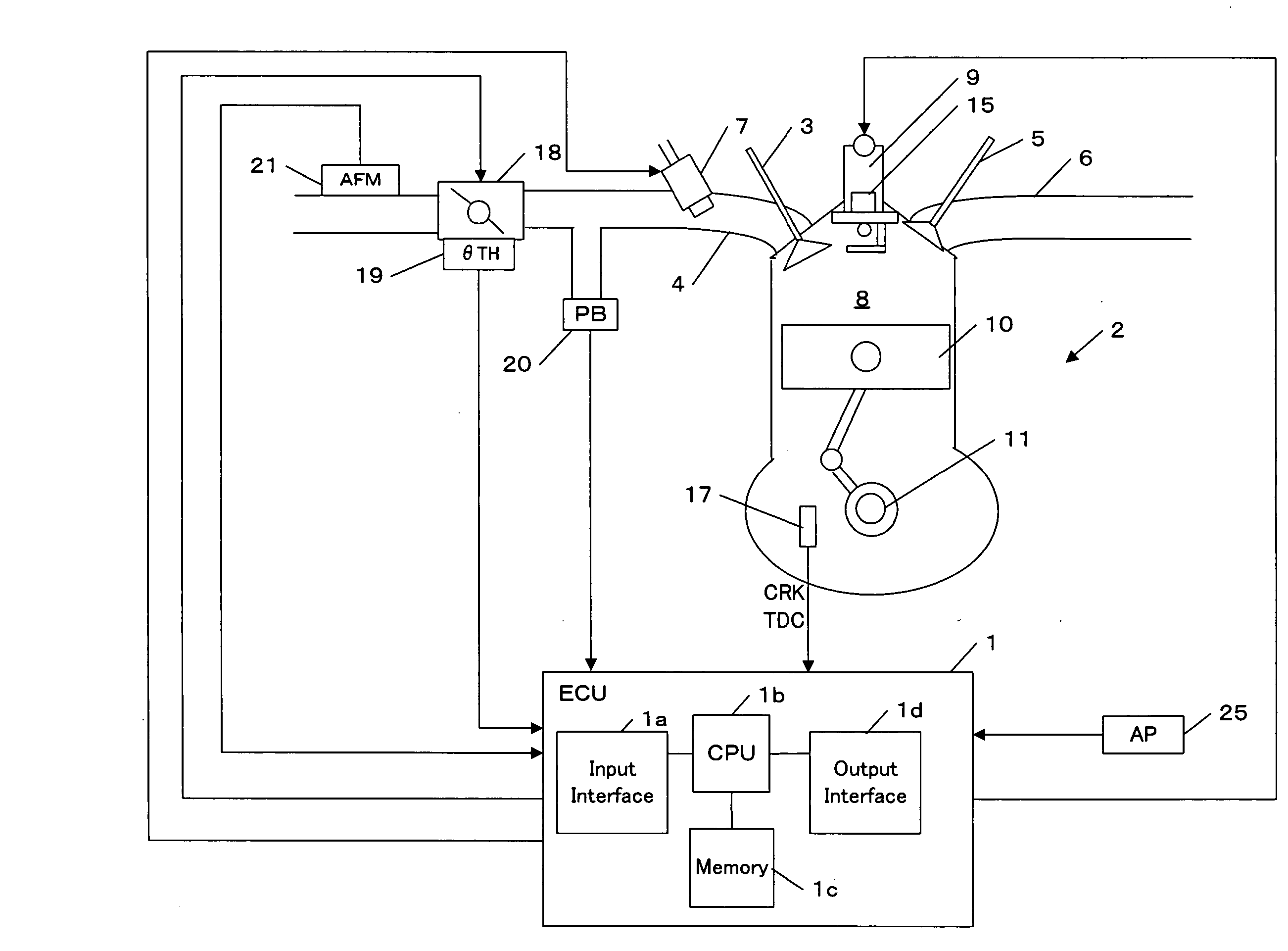
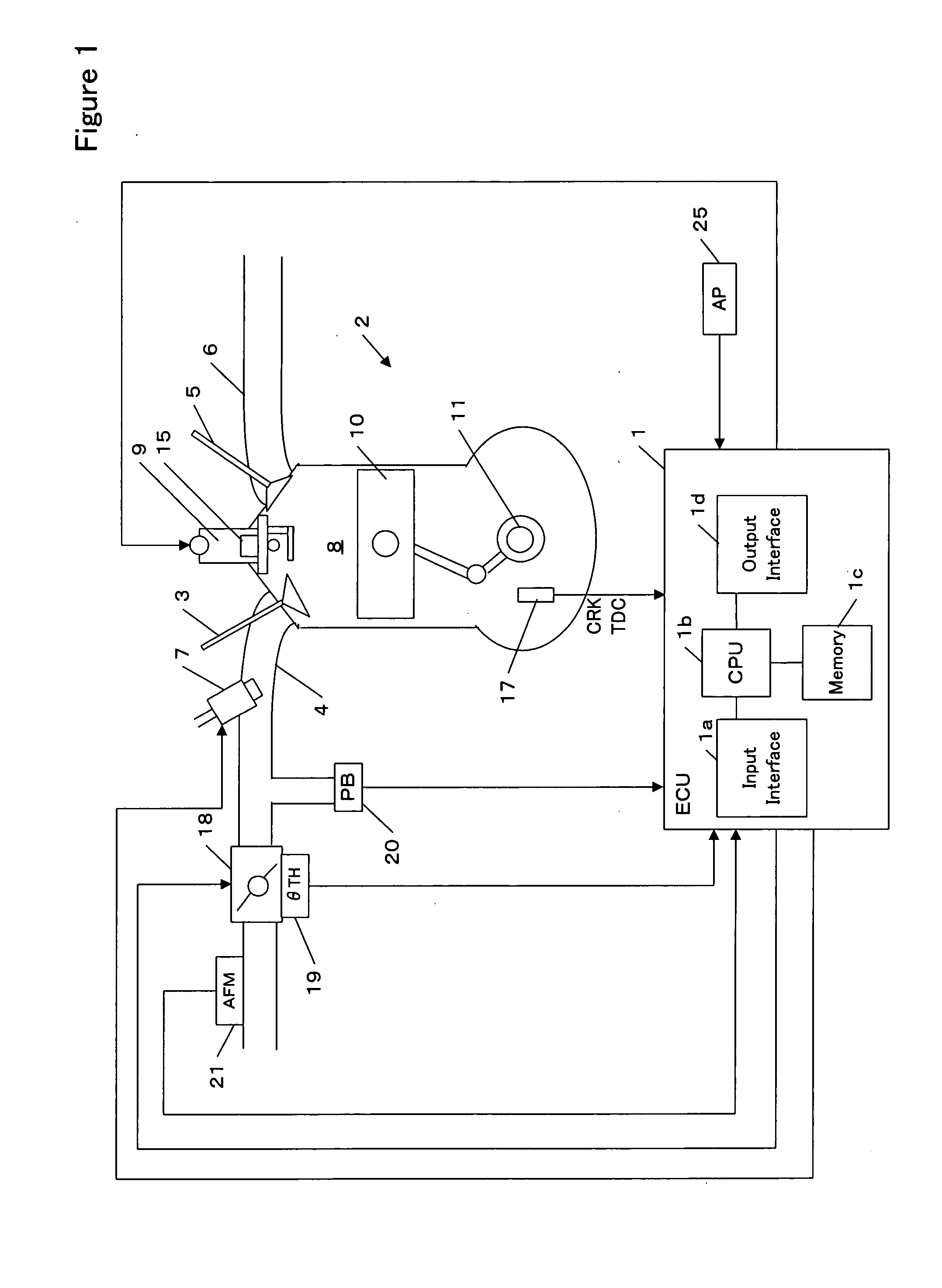
[0039] Referring to the drawings, specific embodiments of the invention will be described. FIG. 1 is a block diagram showing an engine and a control unit for the engine in accordance with one embodiment of the invention.

[0040] An electronic control unit (hereinafter referred to as an ECU) 1 comprises an input interface 1a for receiving data sent from each part of the vehicle, a CPU 1b for carrying out operations for controlling various parts of the vehicle, a memory 1c including a read only memory (ROM) and a random access memory (RAM), and an output interface 1d for sending a control signal to various parts of the vehicle. Programs and various data for controlling each part of the vehicle are stored in the ROM. A program and data for implementing an ignition timing control in accordance with the invention are stored in the ROM. The ROM may be a rewritable ROM such as an EPROM. The RAM provides work areas for operations by the CPU 1b, in which ...


PUM


Abstract

A method of controlling ignition timing of an engine. In the control method, final ignition timing for performing ignition is calculated by adding a variation component to a set ignition timing. According to the final ignition timing, an indicated average effective pressure of an in-cylinder pressure detected when ignition is performed is calculated. An ignition timing characteristic curve indicating the correlation between the indicated average effective pressure and the variation component is estimated and optimal ignition timing is calculated from the characteristic curve. Feedback control for converging the set ignition timing to the optimal ignition timing is then performed. Consequently, the ignition timing is controlled to an optimal ignition timing corresponding to a current operational state of the engine.

Description

BACKGROUND OF THE INVENTION [0001] The present invention relates to an apparatus and method for controlling an ignition timing of an internal combustion engine. [0002] A method for detecting a pressure within the combustion chamber (hereinafter referred to as in-cylinder pressure) of the internal combustion engine (hereinafter referred to as an engine) to control an ignition timing has been proposed. According to a method shown in Japanese Patent Application Unexamined Publication (Kokai) No. 2003-262177, a difference ΔP between the in-cylinder pressure Ptdc at the top dead center (TDC) and the maximum in-cylinder pressure Pmax is compared with a threshold value. If the difference ΔP is less than the threshold value, the ignition timing is advanced. [0003] It is preferable that ignition is performed at an optimum ignition timing. The optimum ignition timing is typically called MBT (Minimum advance for the Best Torque). Ignition at the optimum ignition timing improves the combustion ...

Claims


Application Information

Patent Timeline
IPC IPC(8): G06G7/70F02P5/15F02D35/02F02P5/153
CPCF02D35/027F02D2041/281F02D41/1406F02D41/1408F02D41/187F02D2041/1423F02D2041/1432F02D2041/1433F02D2041/227F02D2200/0404F02D2200/0406F02D2200/1004F02D2200/602F02P5/1523F02P5/1525F02P5/153Y02T10/46F02D35/023F02D41/1403Y02T10/40F02D45/00F02P5/15
Inventor YASUI, YUJIMAEDA, YOSHIOSATO, MASAHIRONAGASHIMA, KEIICHI
Owner HONDA MOTOR CO LTD
Why Eureka
Try Eureka