Eureka AIR delivers breakthrough ideas for toughest innovation challenges, trusted by R&D personnel around the world.

Method of Combusting Oil Shale in a Circulating Fluidized Bed Boiler

a technology of circulating fluidized bed and oil shale, which is applied in the direction of combustion types, furnaces, lighting and heating apparatuses, etc., can solve the problems of high corrosion, high amount of fly ash, etc., and achieve low density, low fluidization velocities, and reduced size

Active Publication Date: 2007-11-29
FOSTER WHEELER ENERGIA OY
View PDF3 Cites 0 Cited by
  • Summary
  • Abstract
  • Description
  • Claims
  • Application Information

AI Technical Summary

Benefits of technology

[0008] More particularly, the object of the present invention is to provide a method of reducing the tendency of fouling of heat transfer surfaces while combusting oil shale in a circulating fluidized bed boiler.
[0009] Another object of the present invention is to reduce chlorine corrosion while combusting oil shale in a circulating fluidized bed boiler.
[0012] According to the present invention, a fluidizing velocity, preferably, of less than about 2.5 m / s, even more prerferably, of less than about 2.0 m / s, is used at the lowest portion of the furnace. It has surprisingly been noticed that such a very low fluidizing velocity provides optimal behavior of the bed when combusting oil shale. A low fluidizing velocity is advantageous in order to avoid excessive attrition of the fuel, and to avoid fouling of heat transfer surfaces in the flue gas path, as well as corrosion related to the fouling.
[0013] According to the present invention, the total rate of introducing gas to the furnace is advantageously such that, in the upper portion of the furnace, the fluidizing velocity is less than about 4.0 m / s, preferably, between 3.0 m / s and 4.0 m / s. This low fluidizing velocity in the upper portion of the furnace is advantageous to avoid excessive amounts of small particles from escaping from the furnace to foul heat exchange surfaces in the flue gas path downstream of the furnace.
[0015] Advantageously, the fuel is crushed to an average particles size of about 1 mm to about 2 mm. Preferably, 90% of the introduced fuel particles are of a size smaller than 10 mm, and 100% smaller than 20 mm. Oil shale particles have a low density, and they do not, when combusted, reduce in size as do typical fuel particles. Instead, they form porous particles which can be fluidized with very low fluidization velocities. Correspondingly, the introduced oil shale particles are advantageously of the above-mentioned optimal size, in order to avoid excessive escaping of bed particles from the furnace, as well as an increased amount of uncombusted carbon in the ash.
[0016] An advantage of combusting oil shale is that the fuel comprises, abundantly, calcium carbonate, CaCO3 to convert, after being calcined to calcium oxide CaO, the sulfur in the fuel to calcium sulfate CaSO4, thus preventing sulfur oxide SO2 emissions to the environment. However, while the calcination is an endothermic reaction, it is advantageous to prevent excess calcination in the furnace. Moreover, it has been observed that the high tendency of attrition of oil shale is partly related to the calcination reaction. Therefore, it has been noticed that the fouling of the heat transfer surfaces decreases when the calcination of CaCO3 is limited by keeping the temperature in the furnace relatively low. The temperature in the furnace is preferably maintained within the range of about 600 degrees Celsius to about 820 degrees Celsius, even more preferably, within the range of about 600 degrees Celsius to about 800 degrees Celsius.

Problems solved by technology

Due to the chlorine, combustion of oil shale suffers from the generation of high corrosion.
Another problem related to oil shale is that it is very friable, producing a high amount of fly ash, which tends to foul the heat transfer surfaces in the flue gas path.

Method used


Image

  • Method of Combusting Oil Shale in a Circulating Fluidized Bed Boiler
  • Method of Combusting Oil Shale in a Circulating Fluidized Bed Boiler

Examples


Embodiment Construction

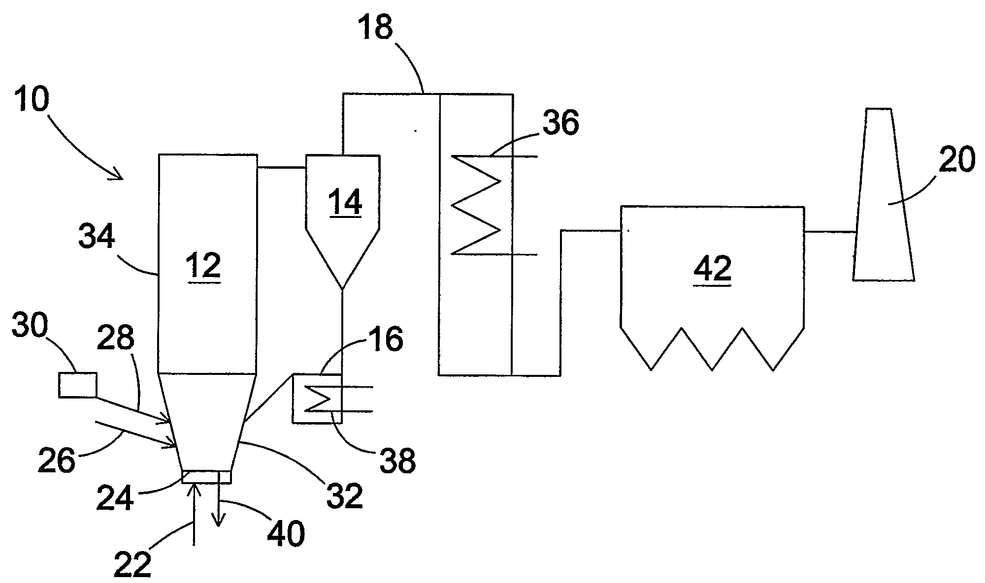
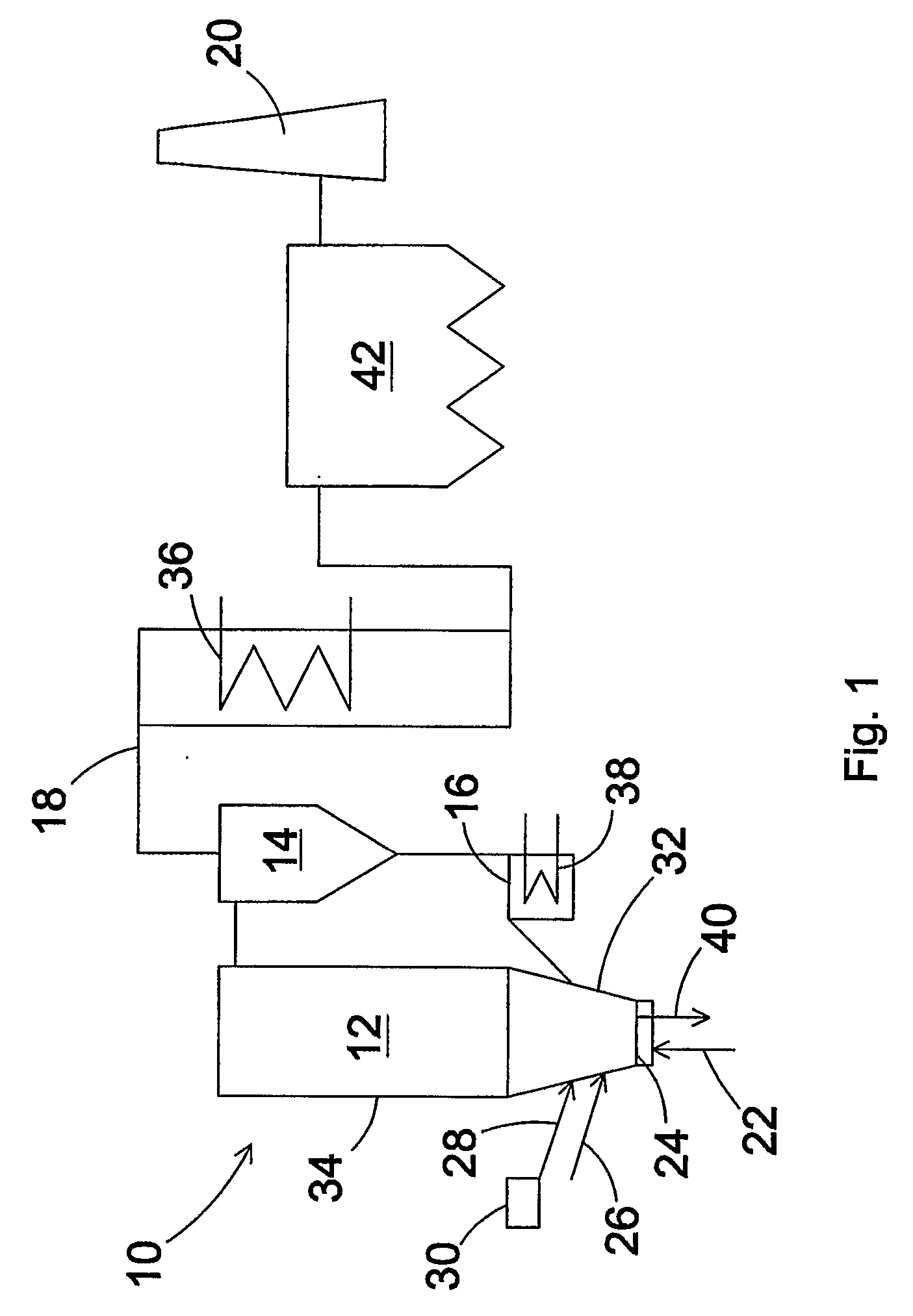
[0019]FIG. 1 shows schematically a CFB boiler 10 comprising a furnace 12, a cyclone separator 14, an external heat exchange member 16 and a flue gas channel 18 for leading flue gases through a stack 20 to the environment. The furnace comprises means 22 for introducing primary air through a bottom grid 24, and means 26 for introducing secondary air at a higher level of the furnace. Secondary air can be introduced at multiple levels, but for the sake of simplicity, they are not shown in FIG. 1.

[0020] The furnace comprises means 28 for introducing fuel, which, when using the present invention, is preferably oil shale. The fuel may alternatively be another fuel which has similar properties as those of the oil shale. Advantageously, the fuel is introduced to the furnace pneumatically. The means 28 for introducing fuel may comprise means 30 for crushing the fuel to a predetermined particle size. Preferably, oil shale is crushed to a mean particle size of 1 to 2 mm. In order to minimize u...


PUM

PropertyMeasurementUnit
fluidizing velocityaaaaaaaaaa

Abstract

A method of combusting oil shale or fuel having similar properties as oil shale in a circulating fluidized bed boiler. The method includes the steps of (a) introducing fuel into a furnace of the circulating fluidized bed boiler, (b) introducing primary oxygenous gas through a bottom grid of the furance, and (c) introducing secondary oxygenous gas to the furnace at a first level above the level of the bottom grid. The primary oxygenous gas is introduced to the furnace at a rate providing below the first level a fluidizing velocity of less than 2.5 m / s, and the primary and secondary oxygenous gases are introduced to the furnace in such a way that the fluidizing velocity below the first level is less than 70% of the fluidizing velocity in the upper portion of the furnace.

Description

BACKGROUND OF THE INVENTION [0001] The present invention relates to the combustion of oil shale in a circulating fluidized bed (CFB) boiler. [0002] In the furnace of a CFB boiler, carbonaceous fuel, such as coal or biofuel, is combusted in a bed of inert material, such as sand, and fluidized oxygenous gas, usually air. The upward velocity of the fluidizing gas in the furnace is usually 5-10 m / s, so as to perform the combustion in a vigorously turbulent bed of particles entrained with the fluidizing gas. Most of the particles escaping from the furnace of a CFB boiler with the flue gas produced in the furnace are separated from the flue gas, usually in a cyclone separator, and are returned to the lower portion of the furnace. [0003] Oil shale, found, for example, in Estonia, the Middle East and North Africa is a special kind of carbonaceous fuel. It comprises 25-40% fossil organic material, in dry mass, with the rest being mineral material having calcium carbonate as the main componen...

Claims


Application Information

Patent Timeline
Patent Type & Authority Applications(United States)
IPC IPC(8): F23C10/00C10B53/06F23C10/14F23C10/20
CPCF23C10/14F23G2900/7013F23C10/20
Inventor HILTUNEN, MATTIKINNUNEN, PERTTISARKKI, JUHA
Owner FOSTER WHEELER ENERGIA OY
Why Eureka
Eureka Blog
Learn More