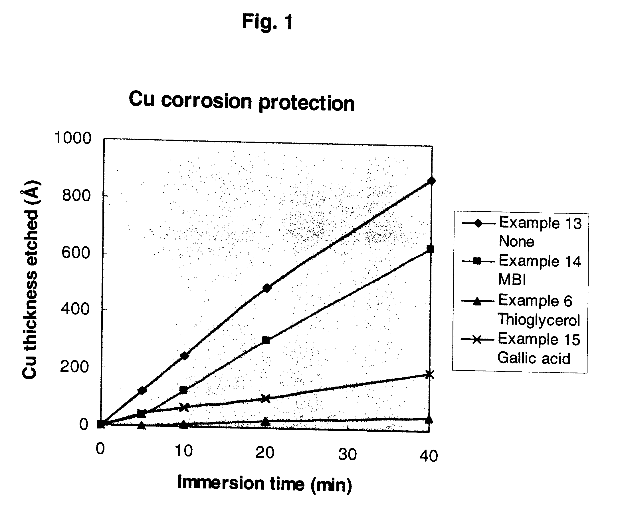
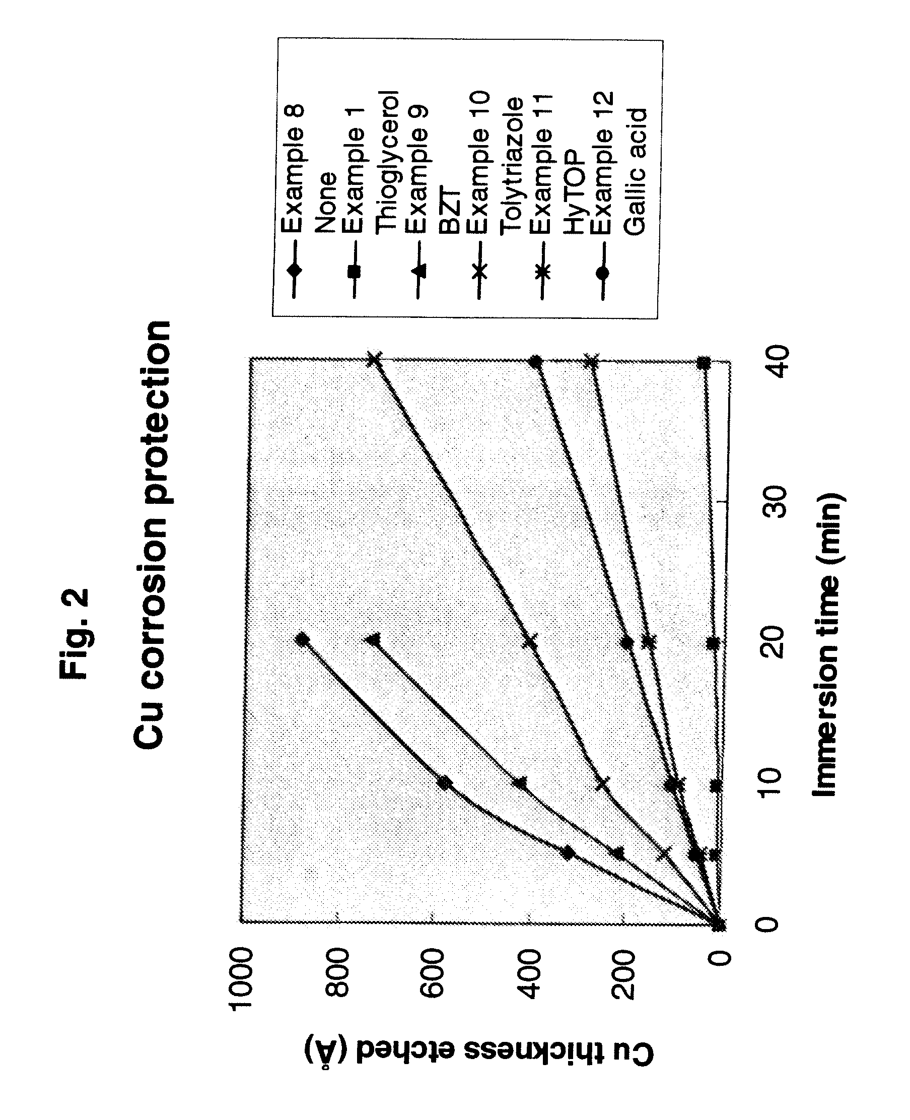
Composition and Method for Photoresist Removal
a technology of photoresist and removal method, which is applied in the field of composition and removal of photoresist, can solve the problems of clogging the filter in the recirculation tool or re-deposit, dissolving bi-layer photoresist for rework, and not being acceptable by current semiconductor customers, and achieves high throughput on single wafer tools
Active Publication Date: 2007-11-29
VERSUM MATERIALS US LLC
View PDF27 Cites 20 Cited by
- Summary
- Abstract
- Description
- Claims
- Application Information
AI Technical Summary
Benefits of technology
[0005]The present invention is a composition for removal of multi-layer photoresist layers on an electronic device substrate for rework of the photoresist on the substrate, comprising; (i) a solvent blend of at least three discrete solvents, (ii) at least one organic sulfonic acid, and (iii) at least one corrosion inhibitor. The present invention is also a method for using the composition. This composition and method succeed in removing such multi-layer photoresist at temperatures less than 65° C. and in contact times under three minutes, allowing high throughput on single wafer tools.
Problems solved by technology
The problem confronted by the electronic fabrication industry is to dissolve bi-layer photoresist for rework processes, which need to be done at less than 65° C. / 3 minutes using single wafer tool process.
Non-dissolved or partially dissolved photoresist can clog the filter in the recirculation tool or re-deposit on the wafer, either of which is not acceptable by current semiconductor customers.
Therefore, the conventional photoresist strippers are not suitable candidates for this application of dissolving bi-layer photoresist for rework processes.
Method used
View moreImage
Smart ImageViewing Examples
Examples
example 1
[0025]
Compoundwt %Di(proplyene glycol) methyl ether51.7p-Toluenesulfonic acid10Tetrahydrofurfuryl alcohol10.3Benzyl alcohol26Thioglycerol2
example 2
[0026]
Compoundwt %Di(proplyene glycol) methyl ether45.9p-Toluenesulfonic acid20Tetrahydrofurfuryl alcohol9.1Benzyl alcohol23Thioglycerol2
example 3
[0027]
Compoundwt %Di(proplyene glycol) methyl ether45.9p-Toluenesulfonic acid201-Octanol9.1Benzyl alcohol23Thioglycerol2
Login to View More PUM
| Property | Measurement | Unit |
|---|---|---|
| Temperature | aaaaa | aaaaa |
| Temperature | aaaaa | aaaaa |
| Temperature | aaaaa | aaaaa |
Abstract
The present invention is a composition for removal of multi-layer photoresist layers on an electronic device substrate for rework of the photoresist on the substrate, comprising; (i) a solvent blend of at least three discrete solvents, (ii) at least one organic sulfonic acid, and (iii) at least one corrosion inhibitor. The present invention is also a method for using the composition. This composition and method succeed in removing such multi-layer photoresist at temperatures less than 65° C. and in contact times under three minutes, allowing high throughput on single wafer tools.
Description
CROSS REFERENCE TO RELATED PATENT APPLICATIONS[0001]This application claims the benefit of U.S. Provisional Patent Application Ser. No. 60 / 809,085 filed 26 May 2006.BACKGROUND OF THE INVENTION[0002]The problem confronted by the electronic fabrication industry is to dissolve bi-layer photoresist for rework processes, which need to be done at less than 65° C. / 3 minutes using single wafer tool process. For the conventional photoresist strippers, the problem can be resolved at high operation temperatures (>75° C.) and long process times (over 10 minutes). For some conventional strippers, photoresist is removed by lifting-off rather than dissolving. Non-dissolved or partially dissolved photoresist can clog the filter in the recirculation tool or re-deposit on the wafer, either of which is not acceptable by current semiconductor customers.[0003]Therefore, the conventional photoresist strippers are not suitable candidates for this application of dissolving bi-layer photoresist for rewor...
Claims
Login to View More Application Information
Patent Timeline
 IPC IPC(8): G03F7/42B08B7/00
CPCH01L21/31133G03F7/426G03F7/32
Inventor WU, AIPINGMARSELLA, JOHN ANTHONY
Owner VERSUM MATERIALS US LLC
Features
- R&D
- Intellectual Property
- Life Sciences
- Materials
- Tech Scout
- Unparalleled Data Quality
- Higher Quality Content
- 60% Fewer Hallucinations
Learn More Browse by: Latest US Patents, China's latest patents, Technical Efficacy Thesaurus, Application Domain, Technology Topic, Popular Technical Reports.
© 2025 PatSnap. All rights reserved.Legal|Privacy policy|Modern Slavery Act Transparency Statement|Sitemap|About US| Contact US: help@patsnap.com


