Multi-graphics processor system, graphics processor and data transfer method

Active Publication Date: 2007-11-29
SONY COMPUTER ENTERTAINMENT INC
View PDF6 Cites 79 Cited by
  • Summary
  • Abstract
  • Description
  • Claims
  • Application Information

AI Technical Summary

Benefits of technology

[0009] The present invention has been made in view of the aforementioned problems, and it is a general purpose of the present invention to provide a flexible multi-graphics processor system adaptable to various environments and

Problems solved by technology

Accordingly, graphics chip manufacturers focus on the development of next-generation graphics chips that have improved performance, and the competition between different graph

Method used


Image

  • Multi-graphics processor system, graphics processor and data transfer method
  • Multi-graphics processor system, graphics processor and data transfer method
  • Multi-graphics processor system, graphics processor and data transfer method

Examples


first embodiment

[0035] A first embodiment shows a multiprocessor system, in which a general-purpose processor and a graphics processor are connected to each other via an input / output interface, and a mechanism for data transfer when the general-purpose processor issues read and write commands to the graphics processor.

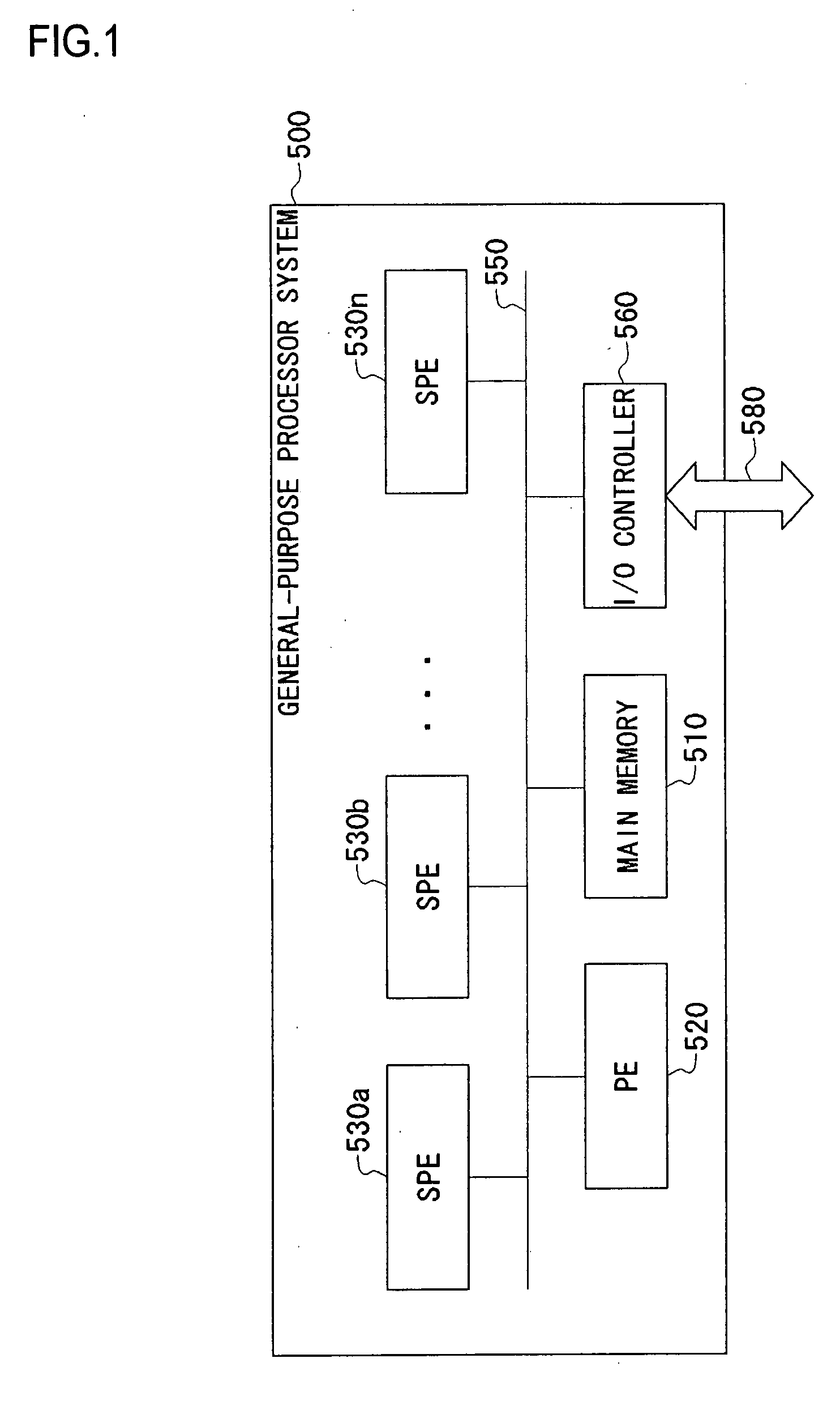
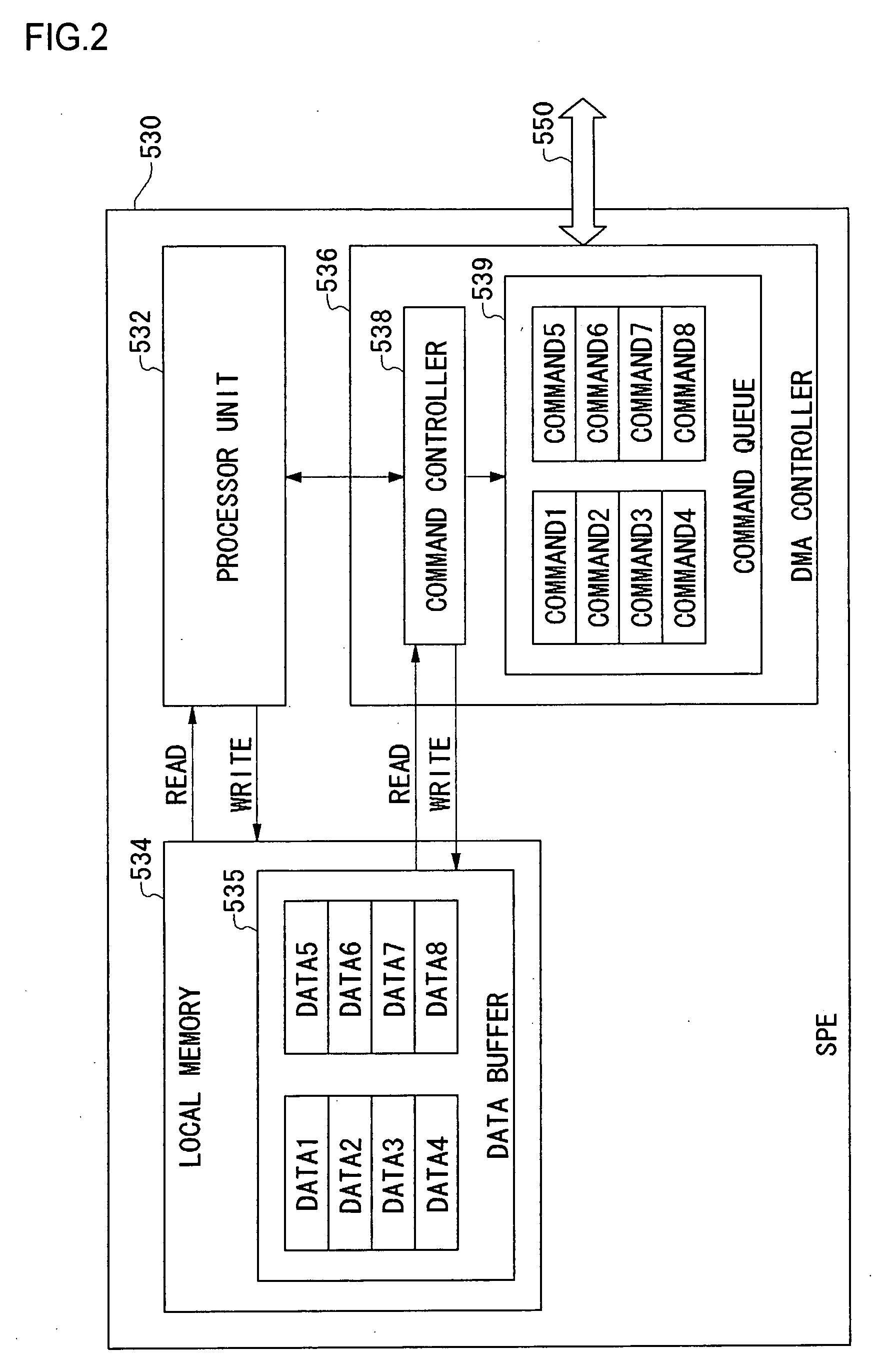
[0036] The configuration of a general-purpose processor system 500 is described with reference to FIGS. 1 and 2. Processing flows for issuance of write commands from the general-purpose processor system 500 to a target device 710a or 710b (hereinafter collectively or individually referred to as target device 710) are described with reference to FIGS. 3A to 3D. Processing flows for issuance of read commands from the general-purpose processor system 500 to a target device 710 are described with reference to FIGS. 4A to 4C. A mechanism that accommodates differences in command execution schemes in an interface connecting the general-purpose processor system 500 and a graphics processing ...

second embodiment

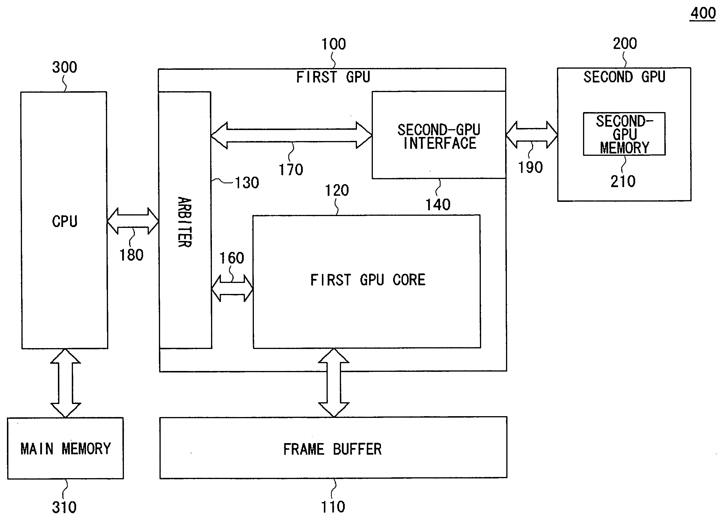
[0105] A second embodiment shows a multi-graphics processor system in which a general-purpose processor is connected to multi-graphics processors, and the system is based on the technology described in the first embodiment. If any one of the multi-graphics processors connected to the general-purpose processor supports only in-order memory access, an interface of such a graphics processor can be designed using the technology described in the first embodiment.

[0106]FIG. 8 is a block diagram of a multi-graphics processor system 400 according to the second embodiment. The multi-graphics processor system 400 includes a first GPU 100, a second GPU 200, a frame buffer 110, a central processing unit (CPU) 300, and a main memory 310.

[0107] The CPU 300 loads a program stored in the main memory 310, executes the program, and reads and writes data to and from the main memory 310. The CPU 300 also centrally controls the whole multi-graphics processor system 400.

[0108] The CPU 300 is described...


PUM


Abstract

A multi-graphics processor system includes a CPU; a first GPU connected to the CPU via an input/output interface; and a second GPU connected to the first GPU via a second-GPU interface. The first GPU is provided with a second-GPU bus for communicating the CPU and the second GPU via the second-GPU interface. The CPU communicates with the second GPU via the second-GPU bus after receiving a signal indicating the timing of the data communication.

Description

BACKGROUND OF THE INVENTION [0001] 1. Field of the Invention [0002] The present invention relates to a multiprocessor system, and more particularly to a multi-graphics processor system, a graphics processor, and a data transfer method for computing rendering data. [0003] 2. Description of the Related Art [0004] High-resolution graphics are widely utilized in personal computers and video game machines. There are, for example, various applications, such as games and simulations which use high-quality 3D-computer graphics, and play video content including a combination of live action and computer graphics. [0005] The rendering quality relies on the performance of graphics chips which are provided in the personal computers or video game machines. Accordingly, graphics chip manufacturers focus on the development of next-generation graphics chips that have improved performance, and the competition between different graphics chips is becoming increasingly fierce. Such advanced graphics are...

Claims


Application Information

Patent Timeline
IPC IPC(8): G06F15/16
CPCG06T1/20G06F9/3879
Inventor SASAKI, NOBUOSHIMIZU, MASAO
Owner SONY COMPUTER ENTERTAINMENT INC
Why Eureka
Try Eureka