Optical Measurement Apparatus

a measurement apparatus and optical technology, applied in the direction of instruments, ion-exchangers, electric regeneration, etc., can solve the problem of relatively large size of the apparatus, and achieve the effect of preventing measurement errors and measuring stably

Inactive Publication Date: 2007-11-29
CITIZEN WATCH CO LTD
View PDF10 Cites 9 Cited by
  • Summary
  • Abstract
  • Description
  • Claims
  • Application Information

AI Technical Summary

Benefits of technology

[0077] Further, in the optical measurement apparatus according to the present invention, the adsorbed ions move under the influence of an electric field, and the ions are thus drained to the outside through the partitioning membrane, accomplishing the regeneration of the ion-exchange resin. When an ion-exchange membrane is used as the partitioning membrane, the regeneration of the ion-exchange resin can be performed while preventing the infiltration of ions opposite in polarity to the ions being drained, and thus permitting continuous removal of interfering substances.
[0078] In this way, in the optical measurement apparatus according to the present invention, by applying an electric field, the pH can be adjusted and the interfering substances can be adsorbed onto the ion-exchange resin for removal, thus accomplishing the regeneration of the ion-exchange resin while permitting continuous removal of the interfering substances.
[0079] In the optical measurement apparatus according to the present invention, when the temperature control solution for controlling the temperature of the sensor section that measures the optical rotation is also used as the waste solution into which the ions adsorbed on the ion-exchange resin are discharged, and heat exchange is performed between the sample and the waste solution to make the temperature of the sample substantially the same as that of the sensor section then, when the sample is introduced into the sensor section a temperature change does not occur, preventing measurement errors from occurring due to a temperature change when measuring the optical rotation, and thus the concentration of component can be measured stably with high accuracy.

Problems solved by technology

However, the method of rotating the polarizer or the analyzer has had the problem that the apparatus size becomes relatively large, because it requires mechanical manipulation to rotate.

Method used


Image

  • Optical Measurement Apparatus
  • Optical Measurement Apparatus
  • Optical Measurement Apparatus

Examples


first embodiment

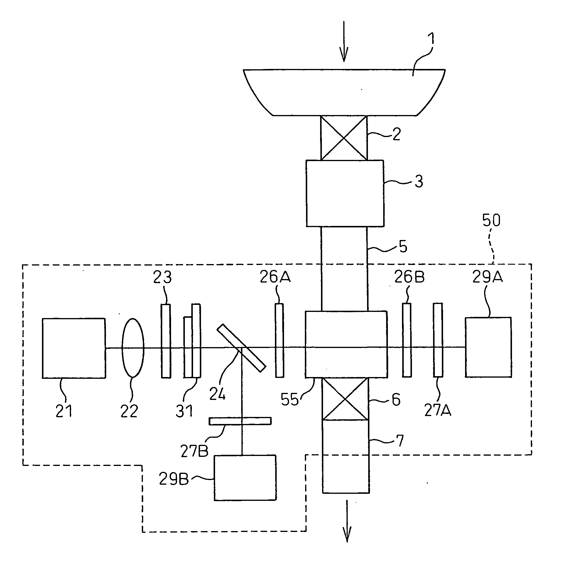
[0107]FIG. 1 is a diagram schematically showing the configuration of an optical measurement apparatus according to the present invention.

[0108] In FIG. 1, a urine collection container 1 is a container for collecting urine, and an electromagnetic valve 2 is provided between the urine collection container 1 and an ion-exchange resin section 3 and is actuated so as not to pass more than a prescribed amount of urine therethrough. The ion-exchange resin section 3 holds therein a weak base anion-exchange resin (for example, WA20 manufactured by Mitsubishi Chemical Corporation) which is detachable. A tube 5 connects between the ion-exchange resin section 3 and a measurement container 55, and conveys the urine therethrough. An electromagnetic valve 6 is provided between the measurement container 55 and a tube 7 and is opened after making a measurement of the urine sample. After the measurement is made, the urine sample is discharged through the tube 7. An optical system 50 is a system for m...

second embodiment

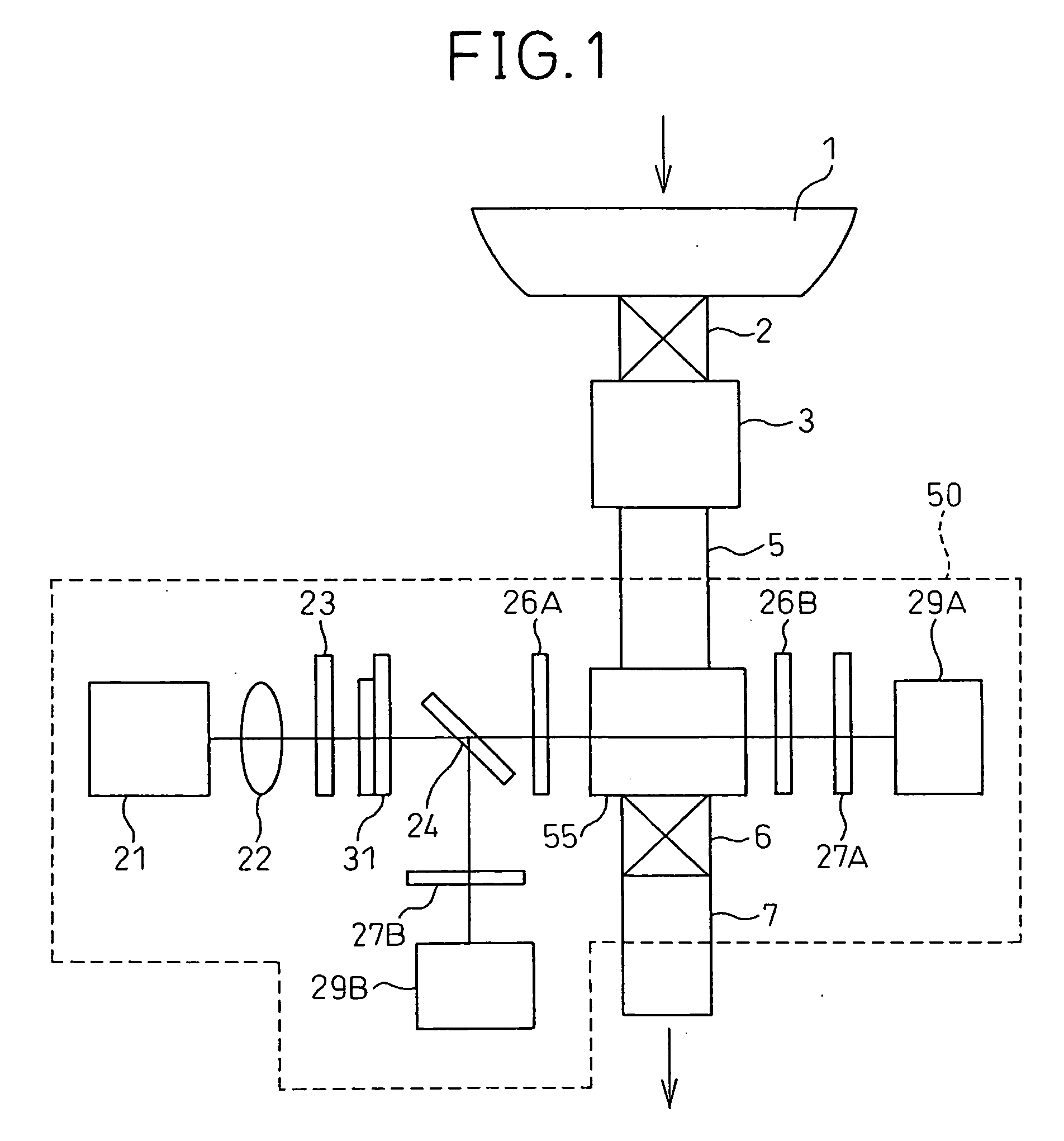
[0121]FIG. 2 is a diagram schematically showing the configuration of an optical measurement apparatus according to the present invention.

[0122] In FIG. 2, the urine collection container 1, the electromagnetic valve 2, and the optical system 50 are identical in configuration to those in the optical measurement apparatus described in the first embodiment. A tube 8 is provided between a tap water faucet and an electromagnetic valve 4, and it conveys tap water therethrough. The electromagnetic valve 4 is provided between the tube 8 and a tube 70 and is actuated to control the flow of water.

[0123] When urine is collected in the urine collection container 1, the electromagnetic valve 2 is opened, allowing the urine to flow into the ion-exchange resin section 3. As in the first embodiment, vitamin C in the urine is removed as it passes through the ion-exchange resin section 3. After that, the urine passes through the tube 70 and is collected in the measurement container 55, where the opti...

third embodiment

[0127]FIG. 3 is a diagram schematically showing the configuration of an optical measurement apparatus according to the present invention.

[0128] In FIG. 3, the urine collection container 1, the electromagnetic valve 2, and the optical system 50 are identical in configuration to those in the optical measurement apparatus described in the first embodiment. A tube 14 is provided between a tap water faucet and a water ionizer 11, and directs tap water into the water ionizer 11. The water ionizer 11 is a device for producing alkaline ionized water and acid water from the tap water, and is provided between an electromagnetic valve 13 and a tube 10. A tube 12 is provided to drain the acid water produced by the water ionizer 11. The electromagnetic valve 13 is provided between the tube 14 and the water ionizer 11 and controls the flow of the tap water to the water ionizer 11. The tube 10 is provided between the water ionizer 11, the electromagnetic valve 13, and the ion-exchange resin sectio...


PUM

PropertyMeasurementUnit
specific rotationaaaaaaaaaa
flow rateaaaaaaaaaa
concentrationaaaaaaaaaa

Abstract

An object of the present invention is to provide an optical measurement apparatus equipped with an ion-exchange resin for pretreating a sample, thereby enabling the concentration of component in the sample to be measured with higher accuracy. The optical measurement apparatus of the present invention includes, in addition to the ion-exchange resin, an optical measurement section for measuring, based on the optical characteristics of the component, the concentration of the component in the sample after the sample is passed through the ion-exchange resin.

Description

FIELD OF THE INVENTION [0001] The present invention relates to an optical measurement apparatus for measuring the concentration of an optically active substance and, more particularly, to an optical measurement apparatus that can highly accurately measure the concentration of an optically active substance in a sample pretreated with an ion-exchange resin. BACKGROUND OF THE INVENTION [0002] In the prior art, it is known to provide, as a means for measuring the concentration of an optically active substance in a sample, a method that obtains the concentration from the optical rotation that a beam of light experiences when it is passed through the sample. On the other hand, enzyme-based methods such as the GOP method are known, for example, for measuring glucose concentrations. In the GOP method, there is a limit to the number of measurements that can be made, because an electrode must be brought into contact with the sample and because of its principle of measurement; as a result, mai...

Claims


Application Information

Patent Timeline
Patent Type & Authority Applications(United States)
IPC IPC(8): G01N1/00B01J39/04B01J41/04B01J47/04B01J49/00G01N21/21G01N30/00G01N30/26G01N30/50G01N30/74G01N30/88G01N30/96G01N33/493
CPCB01J39/046B01J41/046G01N2030/746G01N30/96G01N30/74B01J47/04B01J49/0017B01J49/0052B01J49/0069B01J49/0073G01N21/21G01N2030/0035B01J39/07B01J41/07B01J49/08B01J49/30B01J49/53B01J49/57
Inventor YANO, TAKAKAZUMATSUMOTO, KENJIFUKUDA, TADAHIROSUGIURA, MIHARU
Owner CITIZEN WATCH CO LTD
Why Eureka
Try Eureka