Heat Treatment Apparatus

a technology of heat treatment apparatus and heat treatment tube, which is applied in the direction of chemistry apparatus and processes, pressurized chemical processes, pressure vessels for chemical processes, etc., can solve the problems of deteriorating flatness of the substrate, generating slip lines, and difficult to manufacture lsi with a desired pattern, so as to prevent the occurrence of slippage of the substrate caused by differences in thermal expansion coefficients

Inactive Publication Date: 2007-11-29
KOKUSA ELECTRIC CO LTD
View PDF11 Cites 9 Cited by
  • Summary
  • Abstract
  • Description
  • Claims
  • Application Information

AI Technical Summary

Benefits of technology

[0026] Preferably, the supporting plate is formed into a disk-shape having a diameter smaller than the substrate. Preferably, the supporting plate is formed of silicon (Si). When the substrate is formed of silicon, the substrate and the supporting plate are formed of the same material. Therefore, they have the same coefficient of thermal expansion, and hence occurrence of slippage of the substrate caused by difference in coefficient of thermal expansion can be prevented.

Problems solved by technology

In this case, there is a problem such that when the heat treating is performed at a temperature exceeding 1000° C., a slip dislocation occurs on the substrate, near the supporting strip, which results in generation of a slip line.
When the slip line is generated, flatness of the substrate is deteriorated.
This is lead to a problem such that displacement of mask alignment (displacement of mask alignment due to displacement or deformation of focal point) occurs in a lithography step, which is one of the most important steps in an LSI manufacturing process, and hence it is difficult to manufacture an LSI having a desired pattern.

Method used


Image

  • Heat Treatment Apparatus
  • Heat Treatment Apparatus
  • Heat Treatment Apparatus

Examples


first embodiment

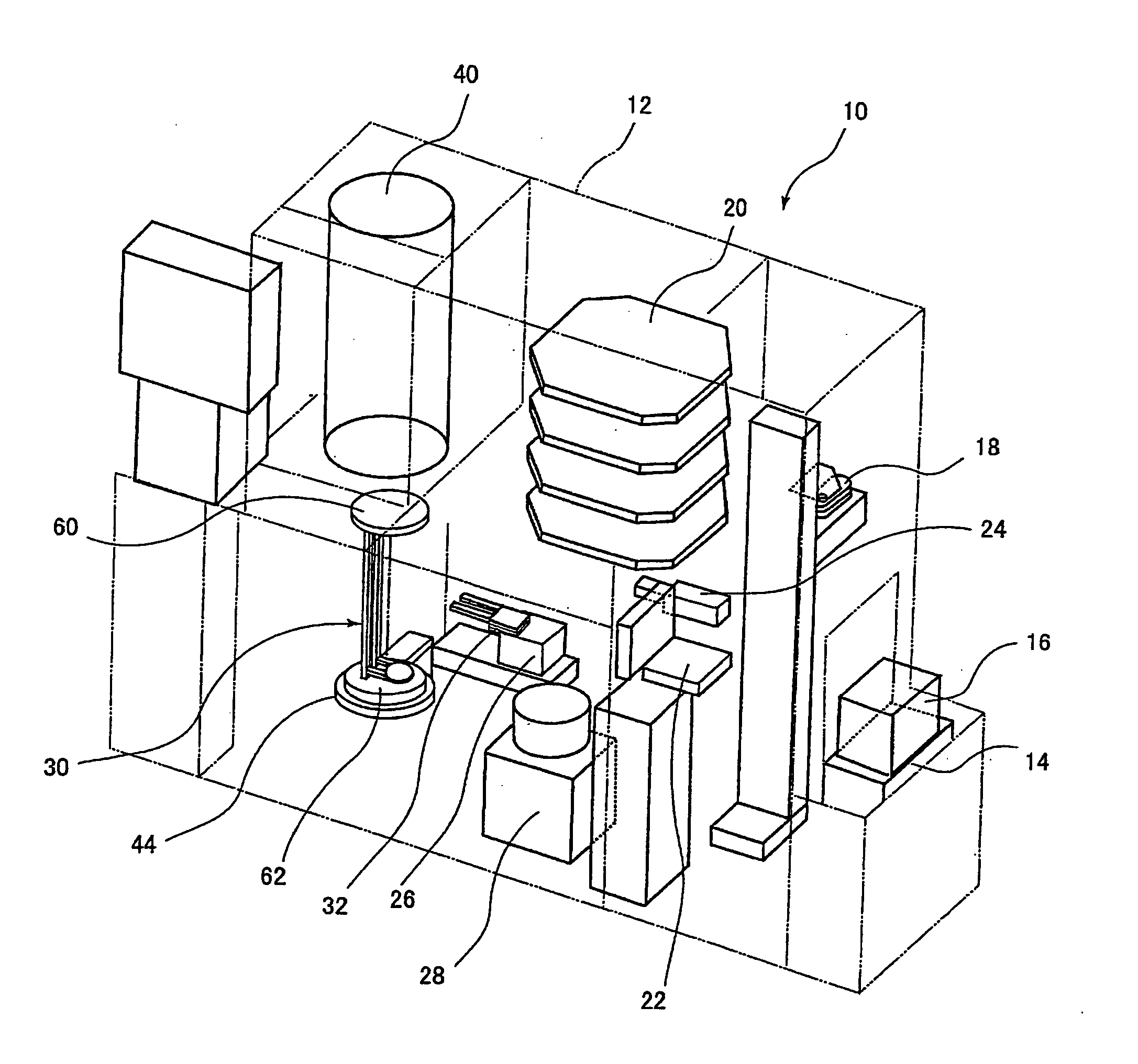
[0079]FIG. 3 and FIG. 4 show a first embodiment, the supporting tool 30 includes a body portion 56 and supporting plates 58. The body portion 56 is formed of silicon carbide or silicon carbide (SiC) impregnated with silicon (Si), and includes an upper plate 60 (shown in FIG. 1) of a disk-shape, a lower plate 62 (shown in FIG. 1) also of the disk-shape, a plurality of, two for example, pillars 64, 64 for connecting the upper plate 60 and the lower plate 62, and supporting strips 66 that connect the pillars 64, 64. The supporting strips 66 are formed integrally with the pillars 64, 64 so as to connect the two pillars 64, 64, and the supporting strips 66 and the pillars 64, 64 are formed into a skeleton (framework) structure. The supporting strip 66 is formed, for example, into an U-shape from above, and extends in the horizontal direction, and includes a projection 68 which projects toward a tweezers 32 insertion side, descried later (the side of the substrate transfer unit 26). A num...

second embodiment

[0118] Subsequently, FIG. 11 and FIG. 12 show a

[0119] The second embodiment is different from the first embodiment described above in the shapes of the supporting strip 66 and the supporting plate 58. In other words, the supporting strip 66 is formed into an M-shape when viewed from above, extends horizontally, and is provided with the projection 68 projecting in a triangle shape toward a tweezers 32 insertion side (the side of the substrate transfer unit 26). A distal end of the projection 68 is protruded from a straight line that connects the two pillars 64, 64 toward the tweezers. A number of the supporting strips 66 are formed in the vertical direction with respect to the pillars 64 at regular intervals, and the supporting plates 58 are supported by a number of the supporting strips 66 respectively. The supporting plate 58 is formed into a disk-shape and the center of the supporting plate 58 is located on the straight line connecting the two pillars 64, 64. The substrate 72 is s...

third embodiment

[0143] FIGS. 16 to 19 show a

[0144] The third embodiment is different from the first embodiment described above in the shapes of the supporting strip 66 and the supporting plate 58.

[0145] In FIGS. 16 to 19, the supporting tool 30 includes the body portion 56 and the supporting plate 58. The body portion 56 is formed of silicon carbide (SiC) or silicon carbide impregnated with silicon, and includes the upper plate 60 (shown in FIG. 1) of the disk-shape, the lower plate 62 (shown in FIG. 1) also of the disk-shape, three sets of, for example, two pillars 64, 64 for connecting the upper plate 60 and the lower plate 62, and supporting strips 66a, 66b, 66c that extend from the three sets of pillars 64, 64. The three sets of pillars 64, 64 are arranged so as to be apart from each other by 90°, two sets on the tweezers 32 insertion side at positions 180° apart from each other and one set on the opposite side from the tweezers 32 insertion side (the side opposite from the side on which the t...


PUM


Abstract

A heat treatment device where intervals between substrates supported by a supporter is reduced so that the number of substrates to be treated can be increased. A heat treatment device has a reaction furnace for treating substrates and a supporter for supporting the substrates in plural stages in the reaction furnace. The supporter has supporting plates in contact with the substrates and supporting members for supporting the supporting plates. A supporting plate and a supporting member are superposed on each other at least a part in the thickness direction.

Description

TECHNICAL FIELD [0001] The present invention relates to a heat treatment apparatus for heat-treating semiconductor wafers or glass substrates. BACKGROUND ART [0002] For example, when heat-treating a plurality of substrates such as silicon wafers using a vertical heat-treating furnace, a supporting tool (boat) formed of silicon carbide is used (see Patent Document 1). This supporting tool is provided with, for example, a supporting strip for supporting the substrate at three points. [0003] Patent Document 1: JP-A-7-45691 [0004] In this case, there is a problem such that when the heat treating is performed at a temperature exceeding 1000° C., a slip dislocation occurs on the substrate, near the supporting strip, which results in generation of a slip line. When the slip line is generated, flatness of the substrate is deteriorated. This is lead to a problem such that displacement of mask alignment (displacement of mask alignment due to displacement or deformation of focal point) occurs ...

Claims


Application Information

Patent Timeline
Patent Type & Authority Applications(United States)
IPC IPC(8): H01L21/00H01L21/673
CPCH01L21/324H01L21/67309H01L21/67303
Inventor NAKAMURA, NAOTONAKAMURA, IWAOSHIMADA, TOMOHARUMOROHASHI, AKIRAYAMAZAKI, KEISHINNAKASHIMA, SADAO
Owner KOKUSA ELECTRIC CO LTD
Why Eureka
Try Eureka