Ultrasonic probe

Active Publication Date: 2007-11-29
KONICA MINOLTA INC
View PDF7 Cites 39 Cited by
  • Summary
  • Abstract
  • Description
  • Claims
  • Application Information

AI Technical Summary

Benefits of technology

[0040] With this configuration, the heat generated by the piezoelectric element can be absorbed and radiated by the material whose thermal conductivity is greater than the backing load member, and the temperature of the ultrasonic probe surface can be lowered. Thus, since even the transmission voltage of the ultrasonic diagnostic apparatus can be raised, the ultrasonic probe where the diagnostic depth can be made deeper

Problems solved by technology

The suppression of the transmission signal to the small value results in the demerit that the diagnostic depth is also shallow.
However, the heat radiation in the configuration of the con

Method used


Image

  • Ultrasonic probe
  • Ultrasonic probe
  • Ultrasonic probe

Examples


first embodiment

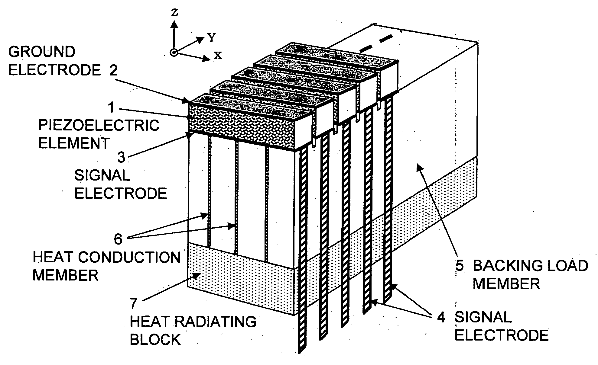
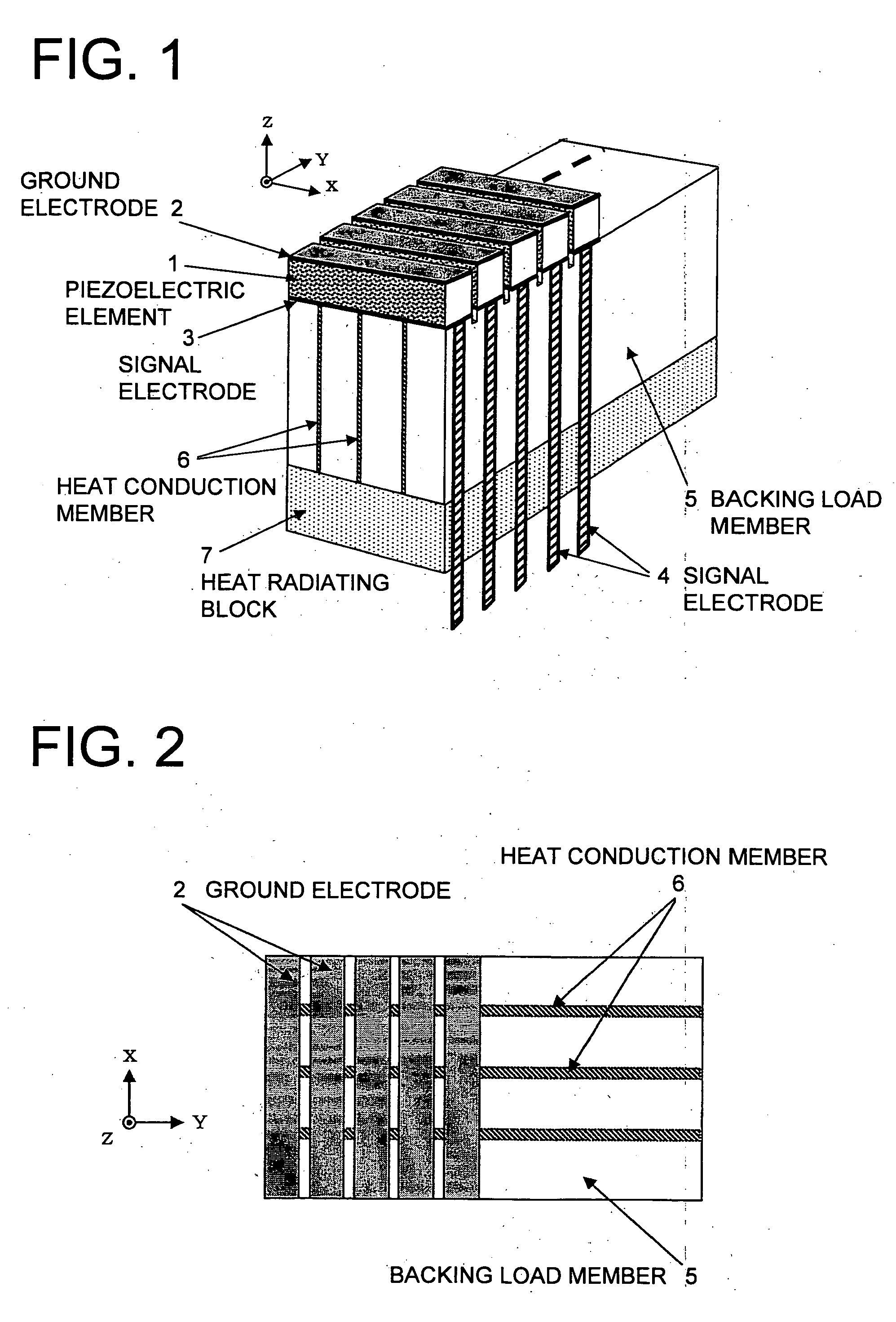
[0050] An ultrasonic probe of an embodiment of the present invention will be described below with reference to the drawings. The ultrasonic probe in the first embodiment of the present invention is shown in FIG. 1 and FIG. 2. FIG. 1 shows the perspective view, and FIG. 2 shows the plan view when FIG. 1 is viewed from above.

[0051] In FIG. 1 and FIG. 2, the ultrasonic probe in the first embodiment is provided with: a plurality of piezoelectric elements 1 which are long in an X-direction, and arrayed in a y-direction and transmit and receive ultrasonic waves in a z-direction (diagnostic depth direction); a plurality of ground electrodes 2 and signal electrodes 3 which are placed on the front surfaces and the rear surfaces of the individual piezoelectric elements 1, respectively; a plurality of signal electrodes 4 for extracting respective signals of the individual signal electrodes 3; a backing load member 5 which has a function for mechanically holding the piezoelectric elements 1 th...

second embodiment

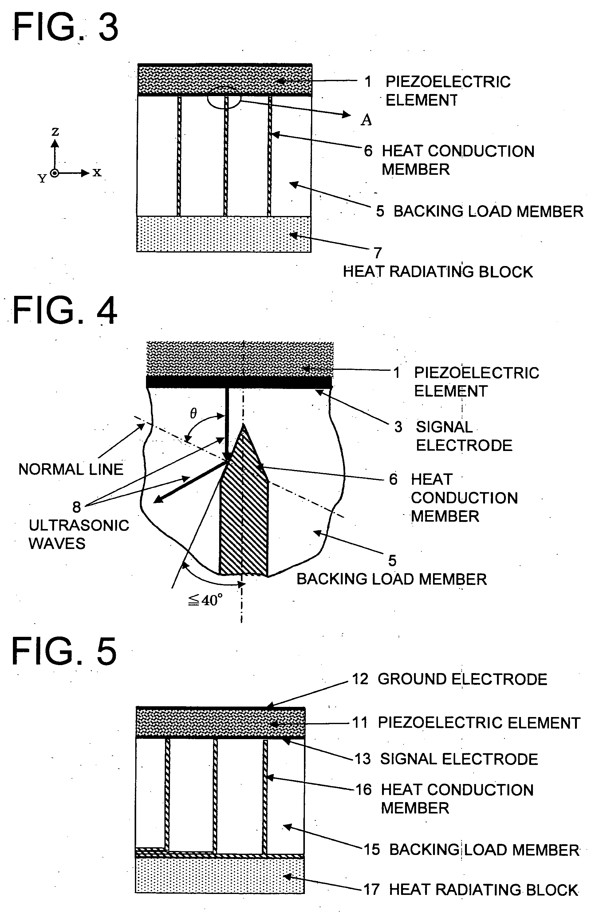
[0062] Next, an ultrasonic probe in the second embodiment of the present invention is shown in FIG. 3 and FIG. 4. By the way, FIG. 4 shows the view where the A-portion of FIG. 3 is enlarged. The configurations of FIG. 3 and FIG. 4 are omitted here because they are equal to the configuration and operation explained in the first embodiment, and the feature of the second embodiment is explained. The second embodiment is characterized in that the end portion (tip portion) on the piezoelectric element 1 side of the heat conduction member 6 has the shape inclined to the surface of a backing load member 5 side of the piezoelectric element 1.

[0063] In such configuration, the piezoelectric element 1 is mechanically vibrated by the voltage applied to the signal electrode 3 and the ground electrode 2 (refer to FIG. 1) which are placed on the front surface and the rear surface of the piezoelectric element 1, respectively, and the ultrasonic waves is generated on both sides of the ground electr...

third embodiment

[0074] Next, the ultrasonic probe in the third embodiment of the present invention is shown in FIG. 5. The configuration of FIG. 5 is equal to the configuration and operation explained in the first embodiment. Thus, it is omitted here, and the feature of the third embodiment is explained. In the third embodiment, a heat conduction member 16 is further placed between a heat radiating block 17 and a backing load member 15.

[0075] As the heat conduction member 16, a material having thermal conductivity greater than that of the backing load member 15 is used, and the heat absorbed in the heat conduction member 16 is radiated in the heat radiating block 17. However, in the case where the heat conduction member 6 and the heat radiating block 17 can be integrally configured, there is no problem. However, depending on the case, there is the case where they cannot be always integrated. For example, in the case of using the PGS graphite sheet with the high degree of orientation where the poly...


PUM


Abstract

A technique that can make a heat radiation effect higher and makes even a transmission voltage of an ultrasonic diagnostic apparatus higher and then makes a diagnostic depth deeper is disclosed. According to this technique, an ultrasonic probe has: a plurality of piezoelectric elements 1 which are long in an X-direction, are arrayed in a y-direction and transmit and receive ultrasonic waves in a z-direction (diagnostic depth direction); a plurality of ground electrodes 2 and signal electrodes 3 which are placed on the front surfaces and the rear surfaces of the individual piezoelectric elements, respectively; a plurality of signal electrodes 4 for extracting respective signals from the individual signal electrodes; a backing load member 5 which has a function for mechanically holding the piezoelectric elements through the signal electrodes and attenuating the unnecessary ultrasonic signal as necessary; a plurality of sheet-shaped heat conduction members 6 which are embedded inside the backing load member and positively transmit the heat generated from the piezoelectric elements; and a heat radiating block 7 which is linked to the heat conduction members on the rear side of the backing load member and radiates the heat transmitted through the heat conduction members.

Description

TECHNICAL FIELD [0001] The present invention relates to an ultrasonic probe used in an ultrasonic diagnostic apparatus and the like. BACKGROUND ART [0002] As a conventional ultrasonic probe, as shown in FIG. 8, a plurality of piezoelectric elements 21 for transmitting and receiving ultrasonic waves are arrayed in a direction orthogonal to the drawing, and a ground electrode 2 and a signal electrode 22 are placed on the front surface and the rear surface of each of the piezoelectric elements 21, respectively (for example, refer to the following patent document 1). An acoustic matching layer 24 for efficiently transmitting and receiving the ultrasonic waves to and from a subject (living body) is formed on the front surface of the ground electrode 2. A backing load member 25, which has a function for attenuating the unnecessary ultrasonic waves transmitted from the piezoelectric element 21 and mechanically holding the piezoelectric element 21 through the signal electrode 22 is placed o...

Claims


Application Information

Patent Timeline
IPC IPC(8): A61B8/00G01N29/24B06B1/06
CPCA61B8/546G10K11/004B06B1/0622
Inventor SAITO, KOETSUTAKEDA, JUNICHI
Owner KONICA MINOLTA INC
Why Eureka
Try Eureka