Laser Device And Operating Method

a laser device and laser beam technology, applied in laser beam welding apparatus, instruments, optics, etc., can solve the problems of increased cost, increased axes, and difficult programming of manipulators, and achieve the effect of simplifying manipulators, simple manner, and easy change of focal lengths

Inactive Publication Date: 2007-12-06
KUKA SYSTEMS
View PDF9 Cites 33 Cited by
  • Summary
  • Abstract
  • Description
  • Claims
  • Application Information

AI Technical Summary

Benefits of technology

[0013] Due to the fact that the focal length can be changed easily, the laser tool can cover a broad range of focal distances and a correspondingly broad range of variations in the working distances. The changing of the lens, which was hitherto necessary, can now be completely eliminated or reduced to a lower extent. In particular, the same laser tool can now be used both at close range and in the remote range as a remote laser. In addition, it is possible due to the adjustment of the focal length to simplify the manipulator and to equip it with fewer axes.
[0014] Furthermore, the laser technique being claimed offers advantages in setting up and teaching the laser device. A pilot laser with a coupled pilot laser beam can now be used in the optically visible wavelength range. The differences between the wavelengths of the pilot laser beam and the working laser beam and the differences in the refraction and focussing charac

Problems solved by technology

This makes programming of the manipulator difficult.
However, the inaccuracy of the path also increases with increasing number of axes.
This leads to higher costs and also to an increased space requirement compared to simpler manipulating systems with a smaller number of axes.
The fixed focal lengths of the la

Method used


Image

  • Laser Device And Operating Method
  • Laser Device And Operating Method
  • Laser Device And Operating Method

Examples


Embodiment Construction

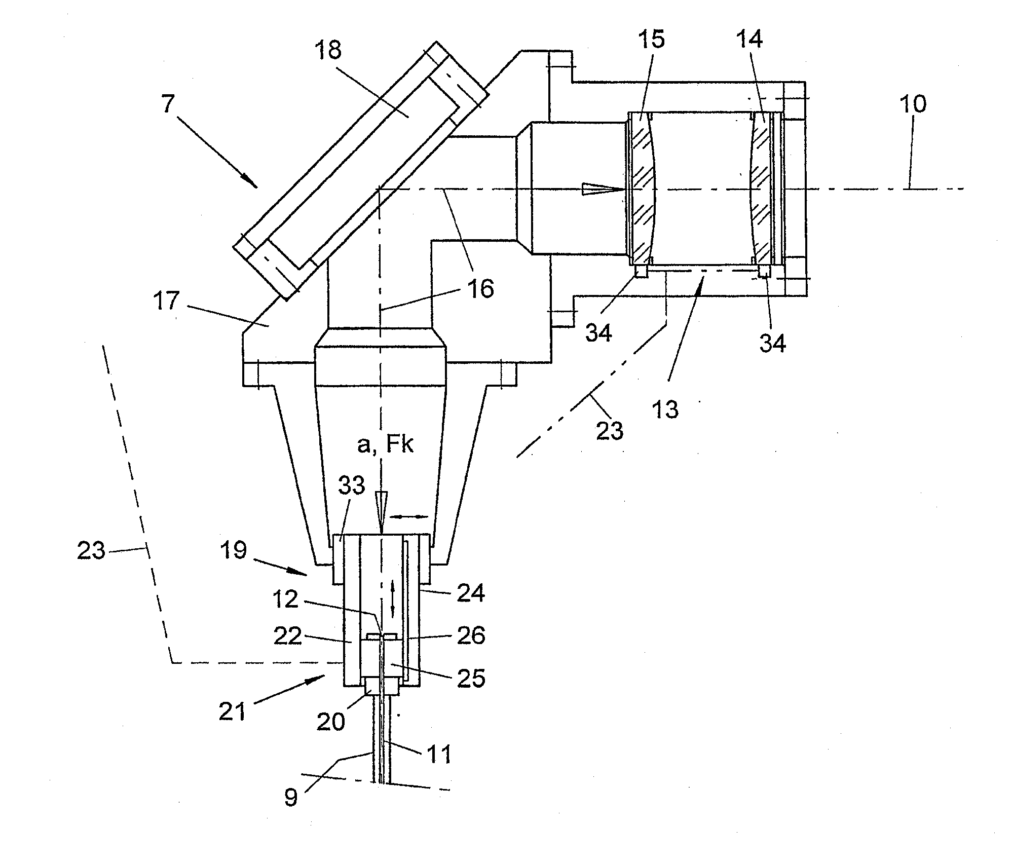
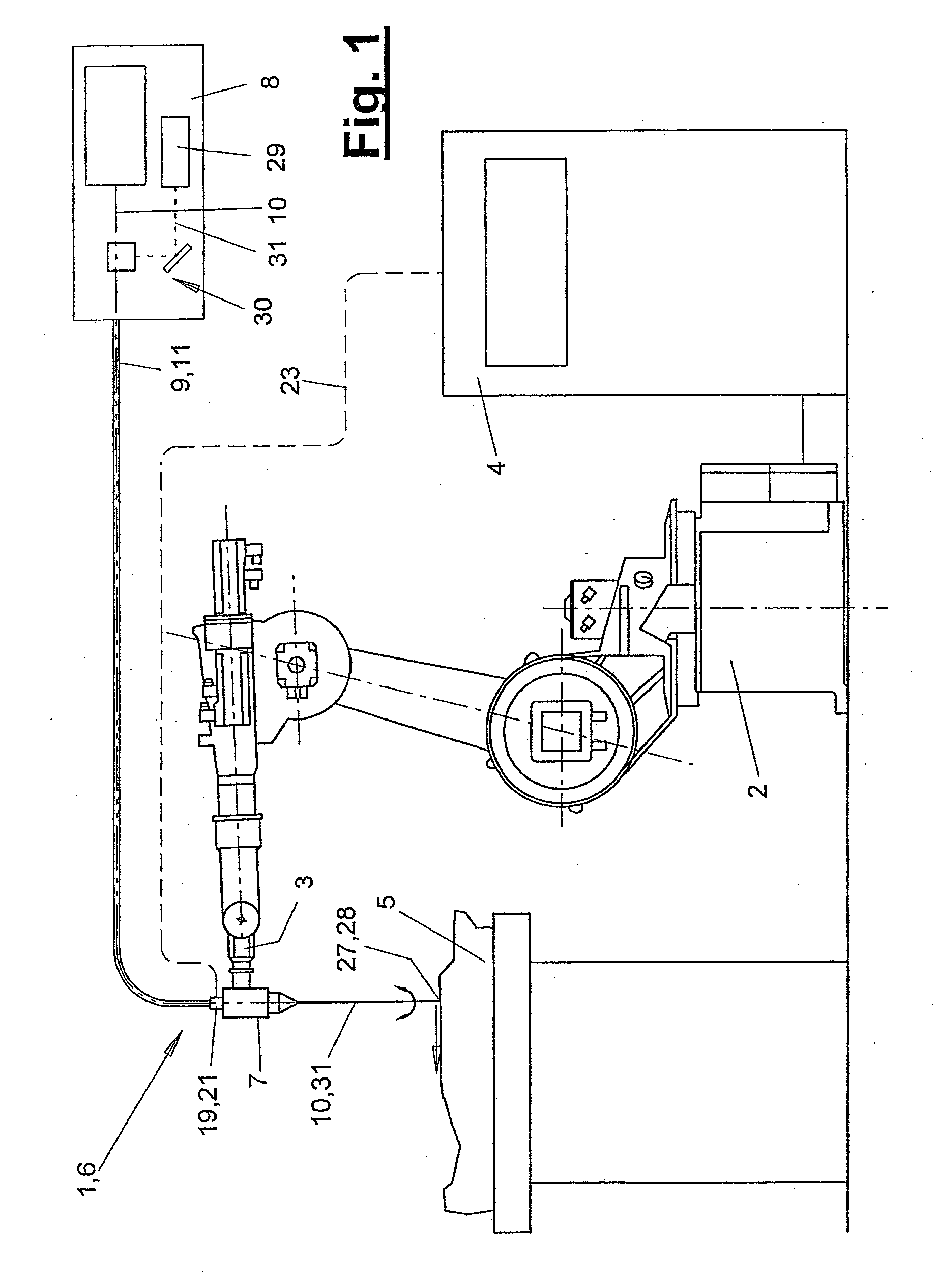
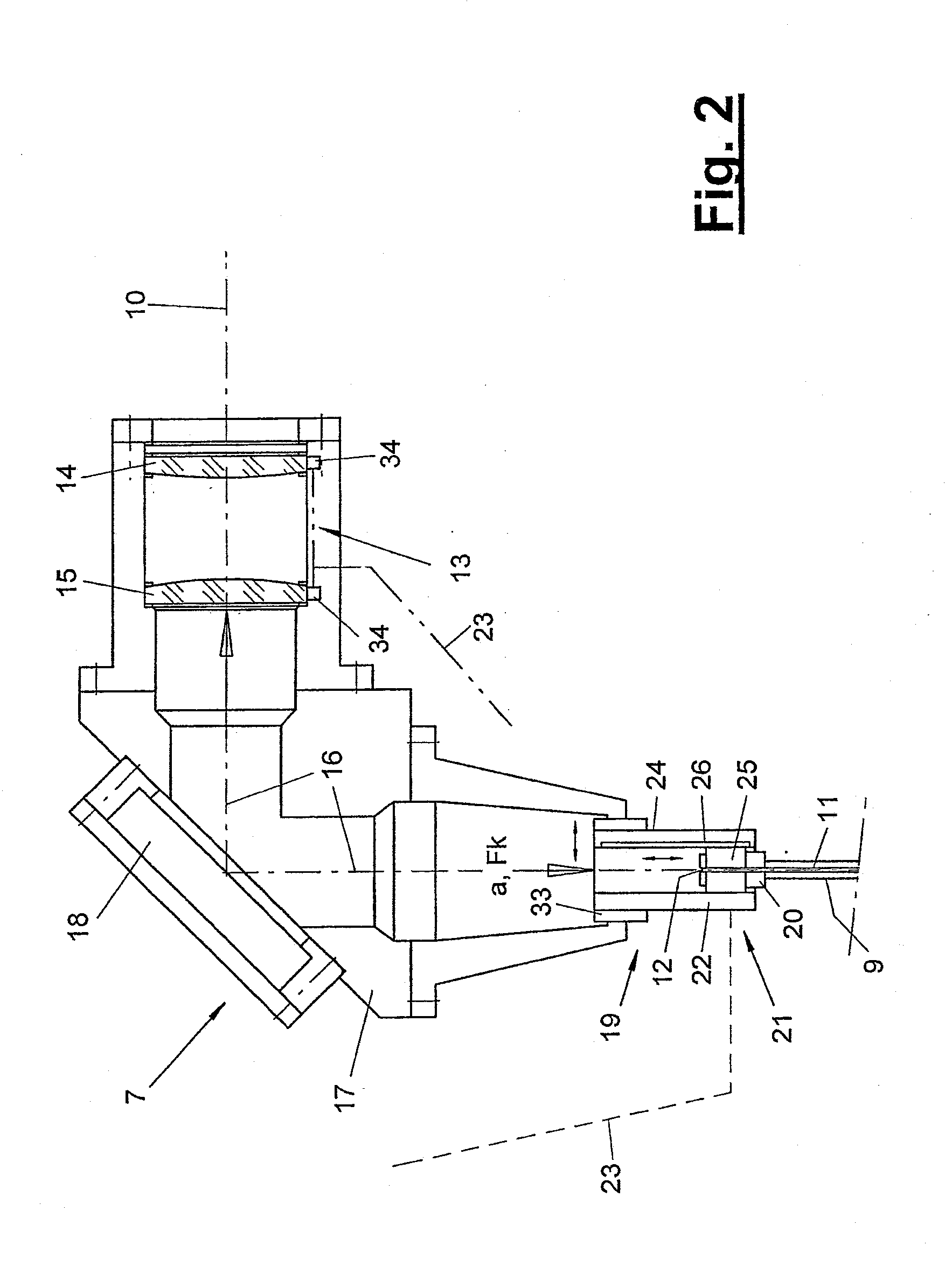
[0042] Referring to the drawings in particular, FIG. 1 shows, in a schematic side view, a laser cell (1), which is equipped with a laser device (6). One or more workpieces (5) are processed in the laser cell (1) with one or more laser beams (10) in any desired manner. These may be, e.g., welding or soldering processes, cutting processes, edge rounding processes or the like.

[0043] The laser device (6) comprises at least one laser tool (7). This is connected in the embodiment shown to a manipulator (2), which may have as many axes as desired. In the embodiment being shown, it is a six-axis articulated arm robot with a multiaxial robot hand (3), to which the laser tool (7) is attached. The robot is a higher-quality and multiaxial embodiment of a manipulator (2). As an alternative, the manipulator (2) may also have a different design, e.g., it may be designed as a linear cross slide system with two axes or the like. The manipulator (2) has only one axis in the simplest case. The axis (...


PUM

PropertyMeasurementUnit
Lengthaaaaaaaaaa
Lengthaaaaaaaaaa
Sizeaaaaaaaaaa

Abstract

A laser device (6) and a corresponding operating method are provided. The laser device (6) is provided with a laser tool (7) including a laser lens system (13) with focussing and collimating lenses and, optionally, a divergent lens (35) and a connector (19) for an optical fiber (11) with a fiber decoupling point (12). The focal length (Ff) of the focussing lens (14) is altered by adjusting the optical separation (b) of the fibre decoupling point (12) from the collimating lens (15) by means of an adjuster device (21).

Description

CROSS REFERENCE TO RELATED APPLICATIONS [0001] This application is a United States National Phase application of International Application PCT / EP2005 / 008456 and claims the benefit of priority under 35 U.S.C. § 119 of German Patent Application DE 10 2004 038 310.3 filed Aug. 5, 2004, the entire contents of which are incorporated herein by reference. FIELD OF THE INVENTION [0002] The present invention pertains to a laser device and a method for operating a laser device. BACKGROUND OF THE INVENTION [0003] Such laser devices are known from practice. They have at least one laser tool, which has a laser lens system with a focussing lens and a collimating lens as well as a connector for an optical fiber. The optical fiber has a fiber decoupling point, at which the laser beam exits. The prior-art laser tools have fixed focal lengths of the laser lens system. To have the focus of the laser beam at the desired point in the workpiece and to generate a focal point of the desired size, it is nec...

Claims


Application Information

Patent Timeline
IPC IPC(8): B23K26/02
CPCB23K26/04G02B6/4296B23K26/0884
Inventor HOELSHER, MANFREDENGLHARD, ANTON
Owner KUKA SYSTEMS
Why Eureka
Try Eureka