

Rotating Electric Machine
a technology of rotating electric machines and rotating shafts, which is applied in the direction of dynamo-electric components, cooling/ventilation arrangement, and magnetic circuit shapes/forms/construction, etc., can solve the problems of unsatisfactory cooling performance, achieve efficient motor cooling, reduce heat resistance between the coil and the cooling oil, and reduce the effect of heat resistan
- Summary
- Abstract
- Description
- Claims
- Application Information
AI Technical Summary
Benefits of technology
Problems solved by technology
Method used
Image

Examples
embodiment 1
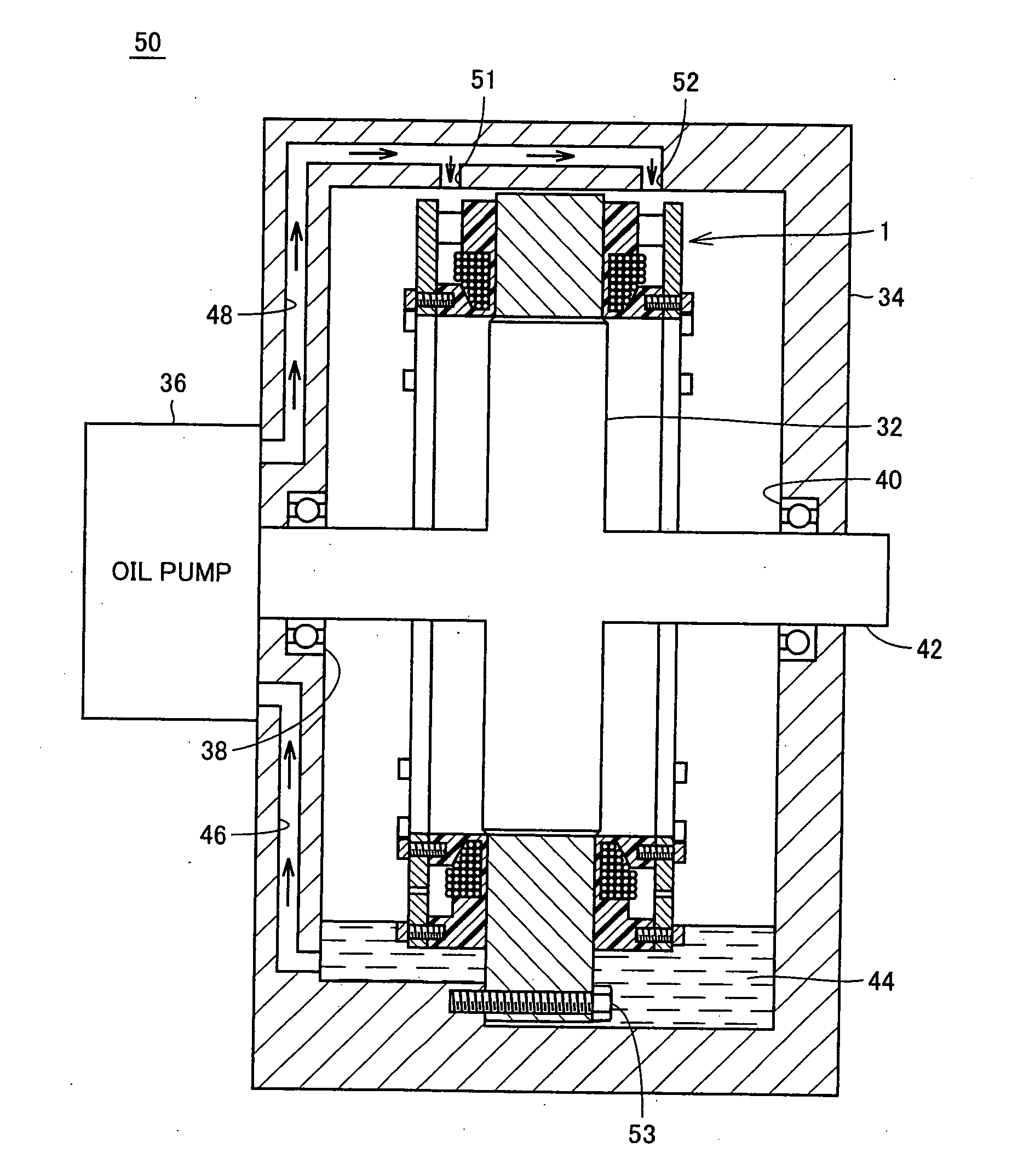
[0040] Embodiment 1 proposes a motor cooling structure that allows operation under severe load conditions and allows reduction in size of a motor in which a coil portion of a stator is molded, by directly liquid-cooling the coil.
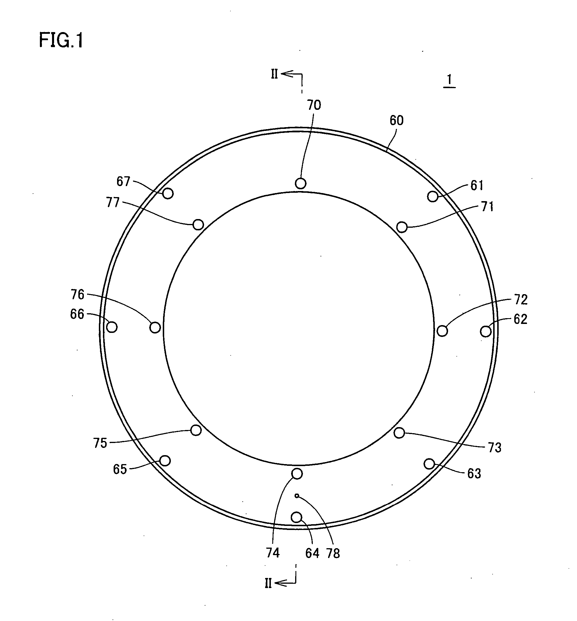
[0041]FIG. 1 is a front view of a stator 1 used in Embodiment 1 of the present invention.
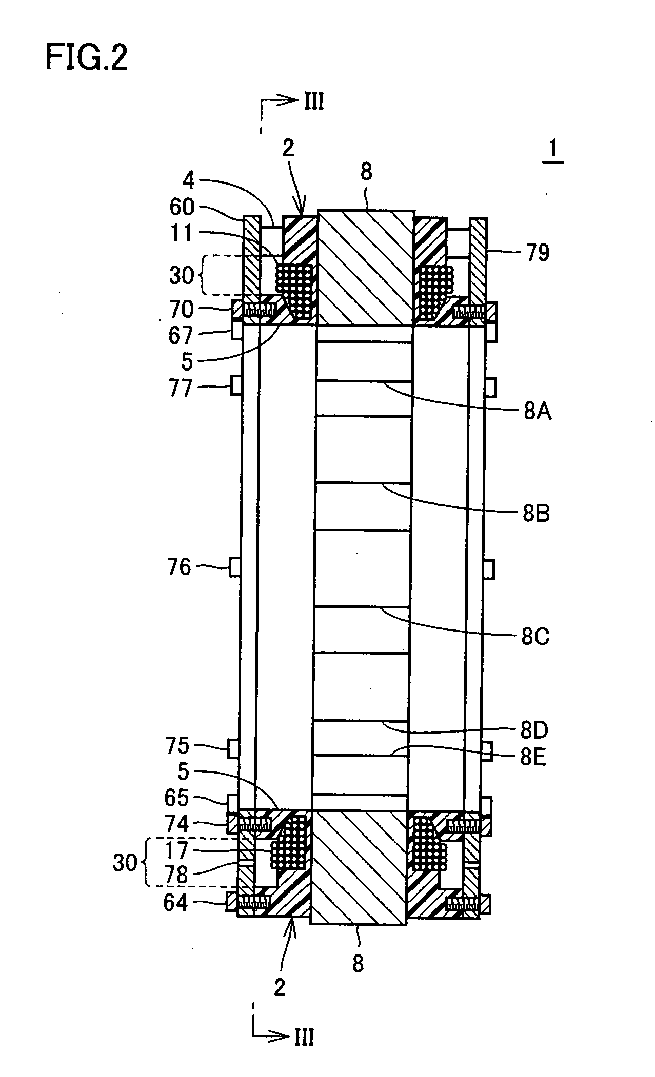
[0042]FIG. 2 is a cross-sectional view taken along the line II-II of FIG. 2.
[0043] Referring to FIGS. 1 and 2, stator 1 has a cylindrical shape accommodating a rotor therein, and includes covers 60 and 79 on opposite side surfaces. Cover 60 is fixed on a mold resin portion 2 of the stator by means of bolts 61 to 67 arranged on an outer circumferential side and bolts 70 to 77 arranged on an inner circumferential side.
[0044]FIG. 3 is a view corresponding to FIG. 2, taken along the direction of III-III, with cover 60 removed.
[0045] Referring to FIGS. 2 and 3, stator 1 includes a stator core 8, coils 11 to 22 wound around core portions of stator core 8, respectively, an...
embodiment 2
[0083] Embodiment 2 corresponds to the structure of rotating electric machine in accordance with Embodiment 1, and according to this embodiment, the quantity of supply of the cooling oil, the shape of flow passage and the cross-sectional area of orifice 78 provided at the cooling oil discharge port are set so that the quantity of cooling oil supply becomes larger than (>) the quantity of discharge.
[0084]FIG. 7 illustrates the flow of cooling oil.
[0085] Referring to FIG. 7, the cooling oil is supplied from cutout portion 7, and the cooling oil flows through the flow passage as shown by the arrows in FIG. 7 and is discharged through orifice 78.
[0086] Let us represent the quantity of cooling oil supply by Qin, dipping height by D1, flow rate coefficient by C, acceleration of gravity by G, initial height of oil surface by h0, and cross-sectional area of orifice 78 by B. Theses values are determined to satisfy the relation represented by the following Equation (1).
Qin≧D1·C·(G / 2h0)1 / 2...
embodiment 3
[0089] In Embodiments 1 and 2, cooling performance is improved by dipping portions of the coils that are exposed from the resin mold in the cooling oil. It is noted, however, that when temperature of motor components such as enamel lines and insulating paper attains high while they are dipped in the cooling oil, these components are subjected to hydrolysis caused by a small amount of water contained in the cooling oil, and as a result, mechanical strength and insulation strength of these components degrade.
[0090] Therefore, while the coils should be dipped in the cooling oil as much as possible to improve cooling performance, it becomes necessary to improve resistance to oil (resistance to hydrolysis) of the enamel line or insulating paper, and material cost for such components increases.
[0091] Embodiment 3 proposes a motor allowing operation under severe load conditions and allowing reduction in size, without necessitating extreme improvement of resistance to oil of components su...
PUM
 Abstract
Description
Claims
Application Information