

Image data transfer method, image processing device, and imaging system
- Summary
- Abstract
- Description
- Claims
- Application Information
AI Technical Summary
Benefits of technology
Problems solved by technology
Method used
Image

Examples
embodiment 1
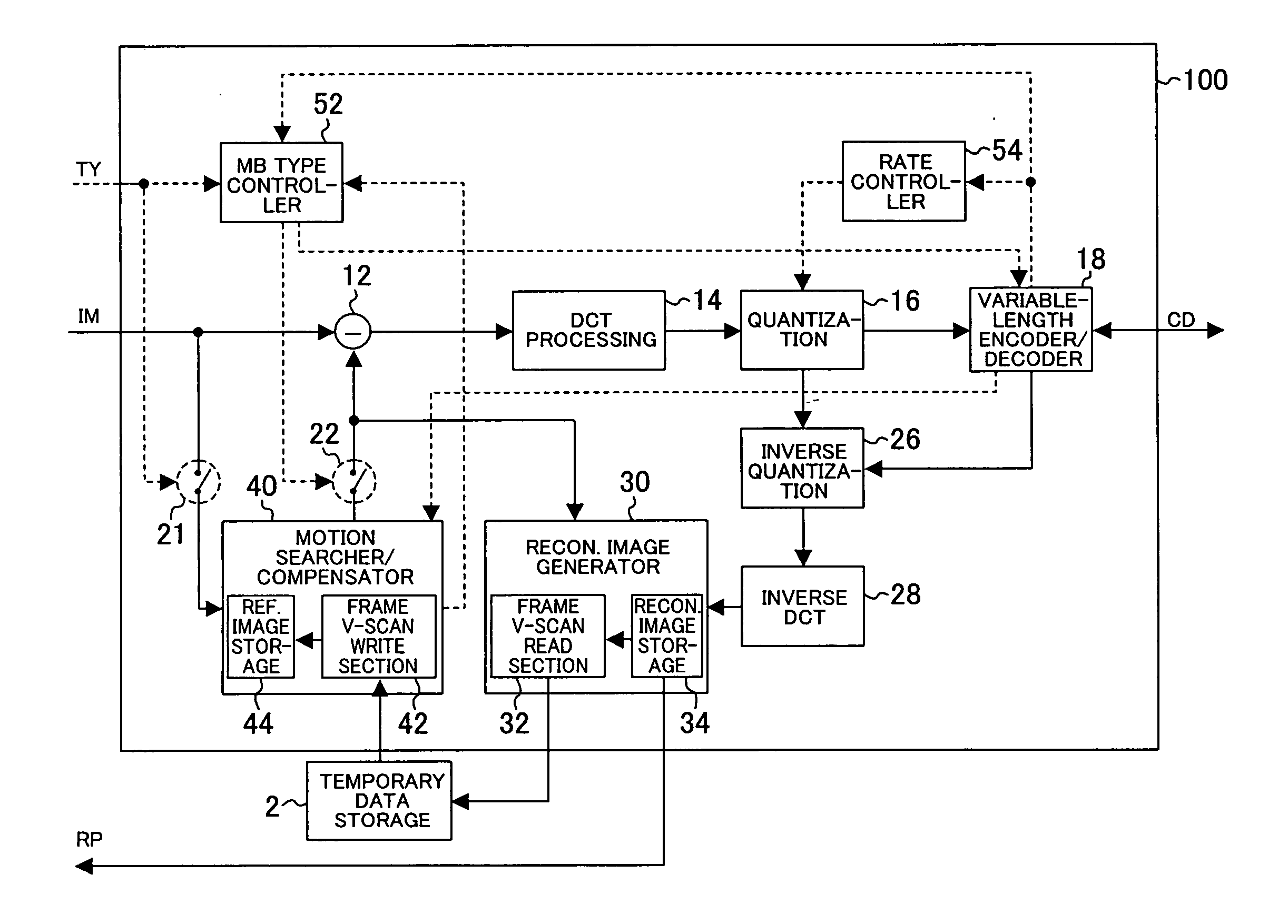
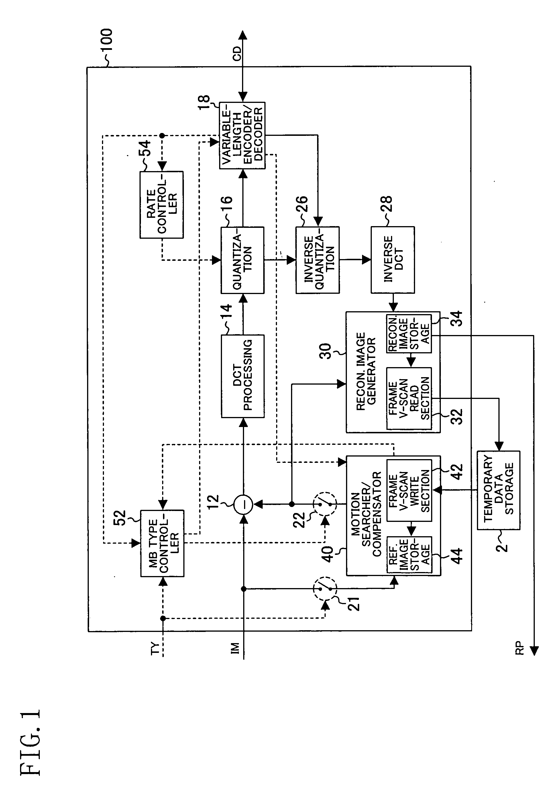
[0093]FIG. 1 is a block diagram showing a structure of an image processing device according to embodiment 1 of the present invention. This image processing device provides improved transfer efficiency of frame pictures.
[0094] The image processing device 100 of FIG. 1 includes a subtractor 12, a DCT (discrete cosine transform) processing section 14, a quantization section 16, a variable-length encoder / decoder 18, switches 21 and 22, an inverse quantization section 26, an inverse DCT processing section 28, a reconstructed image generator 30, a motion searcher / compensator 40, a macroblock (MB) type controller 52, and a rate controller 54. The reconstructed image generator 30 includes a frame vertical scan read section 32 and a reconstructed image storage (first image storage) 34. The motion searcher / compensator 40 includes a frame vertical scan write section 42 and a reference image storage (second image storage) 44.
[0095] The frame vertical scan read section 32 reads data from the r...
embodiment 2
[0178]FIG. 25 is a block diagram showing a structure of an image processing device according to embodiment 2 of the present invention. This image processing device provides improved transfer efficiency of field pictures.
[0179] The image processing device 200 of FIG. 25 is substantially the same as the image processing device 100 of FIG. 1 except that the image processing device 200 includes a reconstructed image generator 230 and a motion searcher / compensator 240 in place of the reconstructed image generator 30 and the motion searcher / compensator 40, respectively. The reconstructed image generator 230 includes a field vertical scan read section 33 and a reconstructed image storage 34. The motion searcher / compensator 240 includes a field vertical scan write section 43 and a reference image storage 44.
[0180]FIG. 26 shows the pixel data of FIG. 13 separated into two fields. FIG. 27 illustrates the order of transfer of the data of FIG. 26 by the field vertical scan read section 33 of ...
embodiment 3
[0209] In embodiment 3, an example of storage of the color difference signals is described. First, a process of a frame picture by the image processing device of FIG. 1 is described.
[0210]FIG. 31 shows data packs of the blue color difference signal and red color difference signal (4:2:0 format) of one macroblock in a frame picture such that the data packs correspond to positions over a display. In FIG. 31, each color difference signal (each having 8 (horizontal) by 8 (vertical) pixels) includes data packs each consisting of 4 horizontally consecutive pixels as does the luminance signal.
[0211]FIG. 32 illustrates an example of mapping of the color difference signals in the temporary data storage 2 of FIG. 1. FIG. 32 shows an example where the blue color difference signal and the red color difference signal are stored in different regions as in embodiment 1. In this case, the frame vertical scan read section 32 of FIG. 1 writes the blue color difference signal of FIG. 31 in the tempo...
PUM
 Abstract
Description
Claims
Application Information