[0021]An object of the present invention is to solve various problems in the prior art and to achieve the following object. That is, an object of the present invention is to provide an image forming apparatus, an image forming method and a process
cartridge, capable of forming an extremely high quality image, which is excellent in fixation properties and causes no change in
color tone when used for a long period of time, and is also free from
abnormality such as decease in density or background smear, using a toner, which is excellent in low-temperature fixation properties and in storage stability and also can reduce generation of
odor.
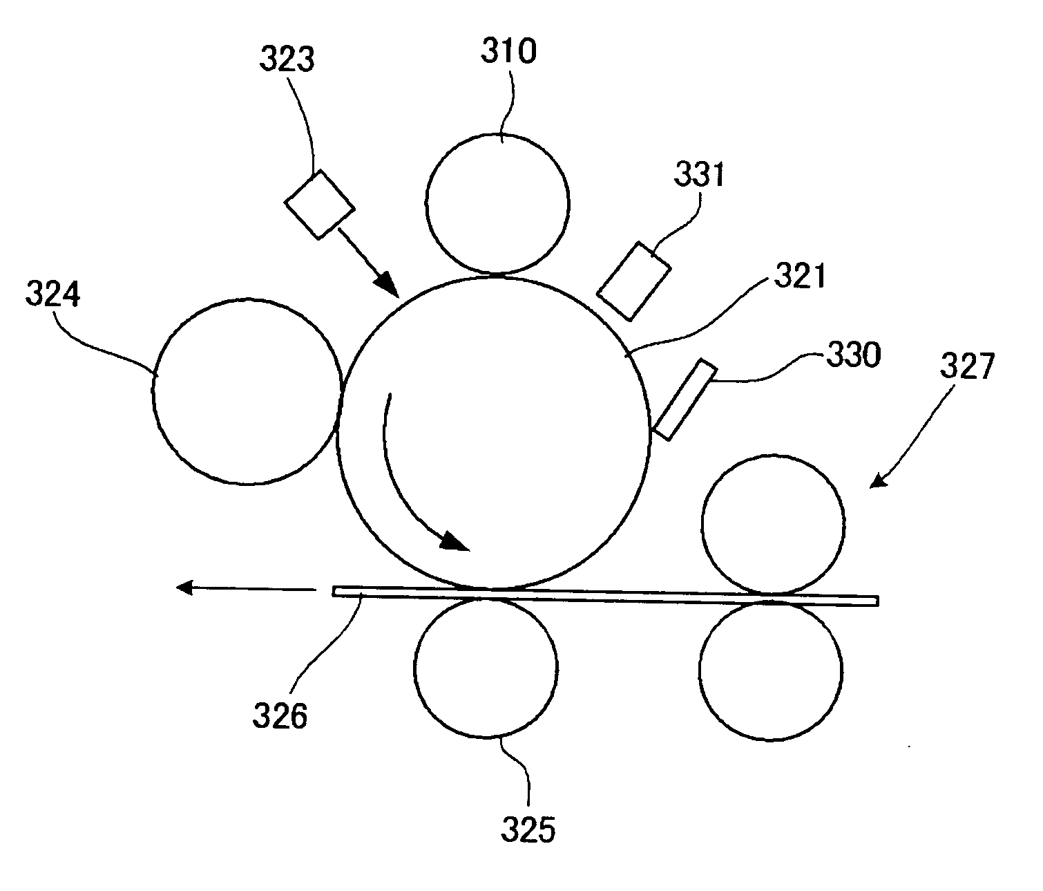
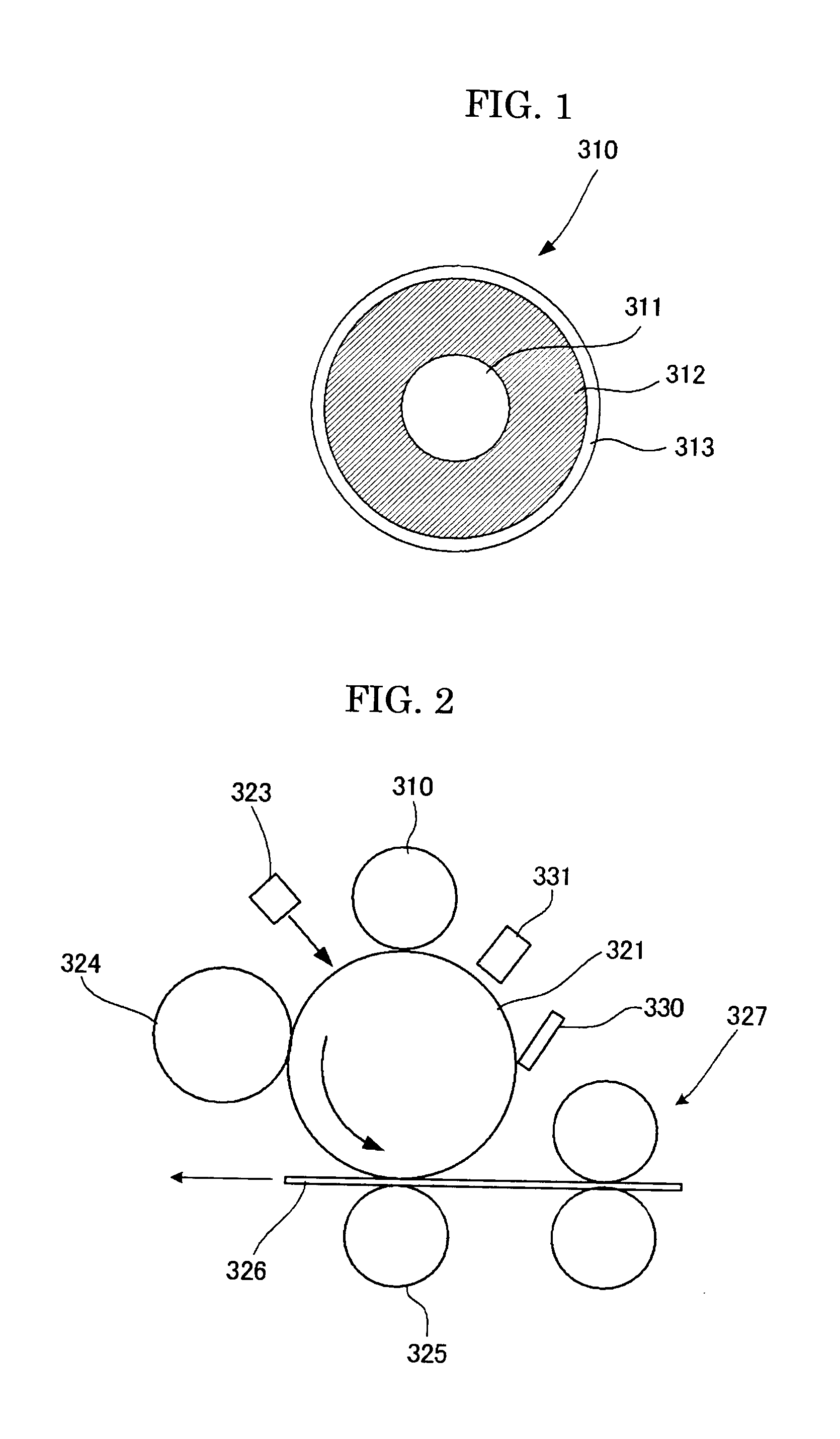
[0072]The image forming apparatus of the present invention comprises at least: a latent electrostatic image bearing member; a charging unit configured to charge a surface of the latent electrostatic image bearing member; an exposing unit configured to
expose the charged surface of the latent electrostatic image to form a latent electrostatic image thereon; a developing unit configured to develop the latent electrostatic image with a toner to form a visualized image; a transferring unit configured to transfer the visualized image onto a recording medium; and a fixing unit configured to fix the visualized image to the recording medium, wherein the toner comprises a binder resin and a coloring agent, and the binder resin comprises a polyester-based resin (A) and a polyester-based resin (B) having a
melting point which is at least 10° C. higher than that of the polyester-based resin (A), and at least one of the polyester-based resins (A) and (B) is a resin derived from a (
meth)
acrylic acid modified
rosin having a polyester unit obtained by condensation
polymerization of an
alcohol component and a
carboxylic acid component containing a (meth)acrylic acid modified rosin. In the image forming apparatus of the present invention, the charging unit configures to uniformly charge the surface of the latent electrostatic image bearing member. By the exposing unit, the surface of the latent electrostatic image bearing member is exposed to form a latent electrostatic image. By the developing unit, the latent electrostatic image formed on the latent electrostatic image bearing member is developed with a toner to form a visualized image. By the transferring unit, the visualized image is transferred onto a recording medium. By the fixing unit, the transferred image transferred onto the recording medium is fixed. At this time, since a resin comprising a polyester-based resin (A) and a polyester-based resin (B) having a
melting point which is at least 10° C. higher than that of the polyester-based resin (A), at least one of the polyester-based resins (A) and (B) being a resin derived from a (meth)acrylic acid modified rosin having a polyester unit obtained by condensation
polymerization of an
alcohol component and a
carboxylic acid component containing a (meth)acrylic acid modified rosin, is used as a binder resin of the toner, it is possible to form an extremely high quality image, which is excellent in low-temperature fixation properties, storage stability, durability and filming resistance and can reduce generation of odor, and also causes no change in
color tone when used for a long period of time and is free from
abnormality such as decease in density or background smear.
[0073]The image forming method of the present invention comprises at least: a charging step of charging a surface of a latent electrostatic image bearing member; an exposing step of exposing the charged surface of the latent electrostatic image to form a latent electrostatic image thereon; a developing step of developing the latent electrostatic image with a toner to form a visualized image; a transferring step of transferring the visualized image onto a recording medium; and a fixing step of fixing the visualized image to the recording medium, wherein the toner comprises a binder resin and a coloring agent, and the binder resin comprises a polyester-based resin (A) and a polyester-based resin (B) having a melting point which is at least 10° C. higher than that of the polyester-based resin (A), and at least one of the polyester-based resins (A) and (B) is a resin derived from a (meth)acrylic acid modified rosin having a polyester unit obtained by condensation polymerization of an alcohol component and a carboxylic acid component containing a (meth)acrylic acid modified rosin. In the image forming method of the present invention, in the charging step, the surface of the latent electrostatic image bearing member is uniformly charged. In the exposing step, the surface of the latent electrostatic image bearing member is exposed to form a latent electrostatic image. In the developing step, the latent electrostatic image formed on the latent electrostatic image bearing member is developed with a toner to form a visualized image. In the transferring step, the visualized image is transferred onto a recording medium. In the fixing step, the transferred image transferred onto a recording medium is fixed. At this time, since a resin comprising a polyester-based resin (A) and a polyester-based resin (B) having a melting point which is at least 10° C. higher than that of the polyester-based resin (A), at least one of the polyester-based resins (A) and (B) being a resin derived from a (meth)acrylic acid modified rosin having a polyester unit obtained by condensation polymerization of an alcohol component and a carboxylic acid component containing a (meth)acrylic acid modified rosin, is used as a binder resin of the toner, it is possible to form an extremely high quality image, which is excellent in low-temperature fixation properties, storage stability, durability and filming resistance and can reduce generation of odor, and also causes no change in
color tone when used for a long period of time and is free from
abnormality such as decease in density or background smear.
[0074]The process cartridge of the present invention comprises at least: a latent electrostatic image bearing member; and a developing unit configured to develop a latent electrostatic image formed on the latent electrostatic image bearing member with a toner to form a visualized image thereon, wherein the toner comprises a binder resin and a coloring agent, and the binder resin comprises a polyester-based resin (A) and a polyester-based resin (B) having a melting point which is at least 10° C. higher than that of the polyester-based resin (A), and at least one of the polyester-based resins (A) and (B) is a resin derived from a (meth)acrylic acid modified rosin having a polyester unit obtained by condensation polymerization of an alcohol component and a carboxylic acid component containing a (meth)acrylic acid modified rosin. Therefore, it is possible to form an extremely high quality image, which is excellent in low-temperature fixation properties, storage stability, durability and filming resistance and can reduce generation of odor, and also causes no change in color tone when used for a long period of time and is free from abnormality such as reduced density and background smear.
[0075]According to the present invention, it is possible to solve the problems in the prior art and to provide an image forming apparatus, an image forming method and a process cartridge, capable of forming an extremely high quality image, which is excellent in fixation properties and causes no change in color tone when used for a long period of time, and is also free from abnormality such as decease in density or background smear, using a toner, which is excellent in low-temperature fixation properties and in storage stability and also can reduce generation of odor.

