Toothed Belt for Use with Oil and Relative Timing Control System

a technology of relative timing control and toothed belt, which is applied in the direction of driving belts, v-belts, ropes and cables for vehicles/pulleys, etc., can solve the problems of high cost of control systems with chains and gears, complex systems of both gears and chains, and inability to operate exclusively with oil lubrication, etc., and achieve the effect of reducing the performance of said bel

Active Publication Date: 2007-12-06
DAYCO EURO
View PDF17 Cites 19 Cited by
  • Summary
  • Abstract
  • Description
  • Claims
  • Application Information

AI Technical Summary

Benefits of technology

[0017] The object of the present invention is therefore to obtain a toothed belt which can be used with oil or even partly immersed in oil without decrease in the performances of said belt and maintaining the necessary mechanical properties of adhesion, resistance to wear, precision of meshing and noise emission.
[0018] A further object of the present invention is to allow chains and gears to be replaced without variations in the dimensions of the control system and therefore to use toothed belts of limited width.

Problems solved by technology

However, both gears and chains are complex systems to produce.
Moreover, both chains and gears produce more noise and function exclusively with oil lubrication.
In addition to these main disadvantages, both the control system with chains and the one with gears are very costly.
However, none of the prior art toothed belts have a high resistance to wear and generally operation in direct contact with oil facilitates breakage of the belt which therefore has a reduced average life.
Therefore, no toothed belt to be used with oil or partly immersed in oil is capable of withstanding the duration tests established for use in vehicle drive systems.
Due to the limited extension in width of the belt to be used, it would be more probable for malfunction caused by the overall decrease in modulus, for example poor meshing, to occur.
However, this alternative solution causes problems of adhesion between the material forming the resistant insert and the mixture of the body and, moreover, materials with a high modulus generally have a much higher cost than the glass resistant inserts currently used.

Method used


Image

  • Toothed Belt for Use with Oil and Relative Timing Control System
  • Toothed Belt for Use with Oil and Relative Timing Control System
  • Toothed Belt for Use with Oil and Relative Timing Control System

Examples


example 1

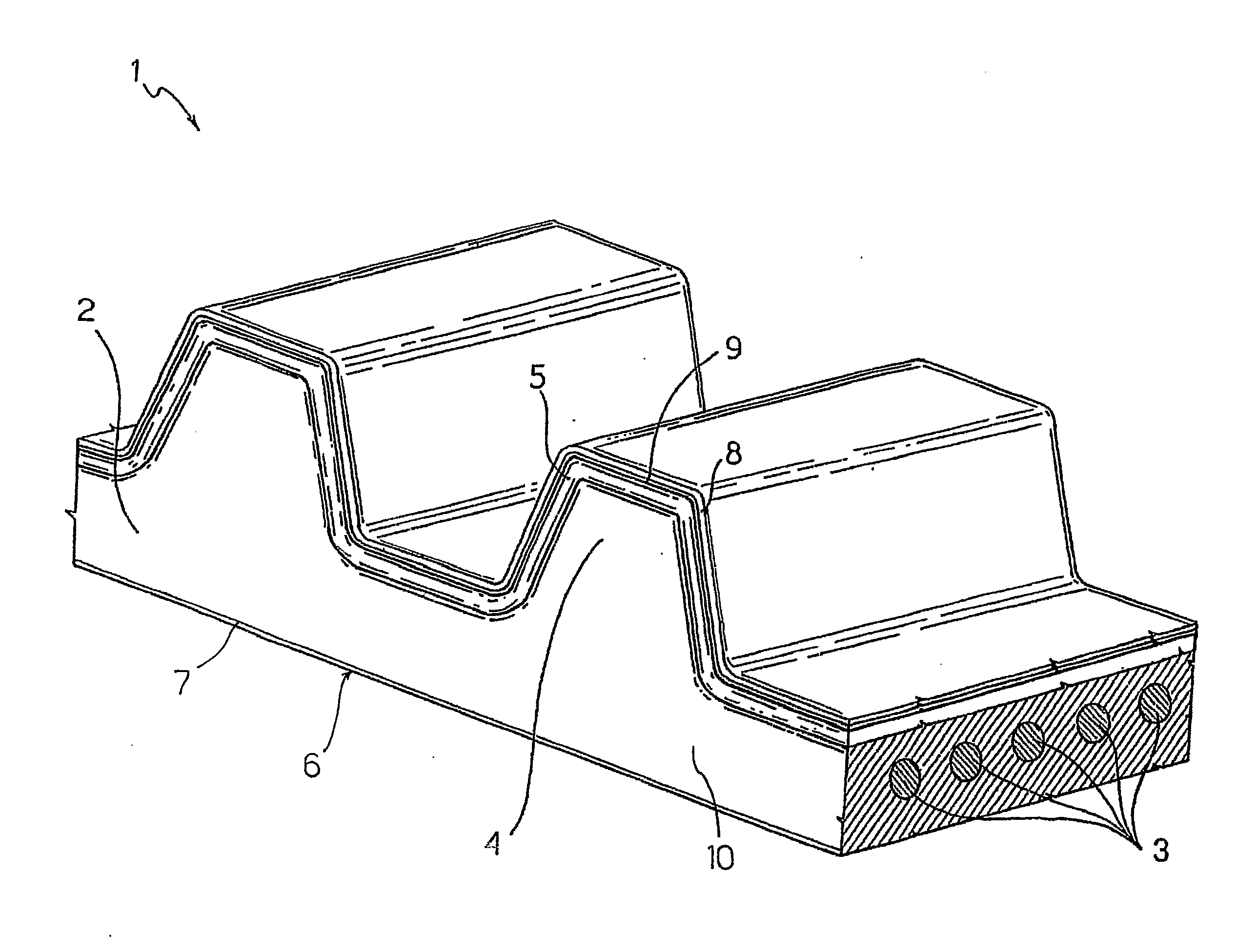
[0088] Table 2 indicates the properties of a fluorinated plastomer usable in a resistant layer 8.

TABLE 2ZONYL MP 1500Average density ASTM D 1457350-400g / lMelting point ASTM D 1457325 ± 10°C.Distribution of particle sizeAverage 6μm(Laser Microtac)Specific surface area (Nitrogen11absorption)

example 2

[0089] Table 3 indicates the properties of an elastomeric material in a resistant layer 8.

TABLE 3ZETPOL 1010Bound acrylonitrile weight %44%Mooney viscosity MS 1 + 4 ml 100° C.78-92Specific gravity0.98 (g / cm3)

example 3

[0090] Table 4 indicates the chemical composition of a resistant layer 8 produced according to the present invention. This resistant layer has a thickness of 0.250 mm.

TABLE 4Elastomeric material as in example 2100 phrFluoropolymer-based additive as in Example 1125 phrPeroxide 6 phr


PUM

PropertyMeasurementUnit
weight %aaaaaaaaaa
lengthaaaaaaaaaa
lengthaaaaaaaaaa

Abstract

Toothed belt for use with oil comprising a body and a plurality of teeth extending from at least a surface of the body; the teeth are covered by a coating fabric. The toothed belt comprises a plurality of resistant inserts produced from at least a first and a second material. Preferably, the resistant inserts are constituted by glass fibres and carbon fibres. Preferably, a resistant layer is made to adhere over the coating fabric, said layer comprising a fluorine based plastomer with the addition of an elastomeric material, wherein the plastomer is present in a greater amount than the elastomeric material. The elastomeric material forming the body of the belt is preferably a copolymer obtained from a diene monomer and a monomer containing nitrile groups, wherein the nitrile groups are between 33% and 49%, preferably 39 weight % with respect to the copolymer.

Description

TECHNICAL FIELD [0001] The present invention relates to a toothed belt and, in particular, a toothed belt for use with oil and to the relative timing control system. BACKGROUND ART [0002] Toothed belts generally comprise a body of elastomeric material, embedded in which are a plurality of longitudinal filiform resistant inserts, also called “cords”, and a plurality of teeth covered by a coating fabric. [0003] Each component of the belt contributes towards increasing the performances in terms of mechanical resistance, to decrease the risk of breakage of the belt and increase the specific transmissible power. [0004] The coating fabric of the belts increases the abrasion resistance and hence protects the working surface of the belt from wear which is due to rubbing between the sides and the slopes of the teeth of the belt and the sides and the bottoms of the grooves of the pulley with which the belt interacts. Moreover, the coating fabric decreases the coefficient of friction on the wo...

Claims


Application Information

Patent Timeline
Patent Type & Authority Applications(United States)
IPC IPC(8): F16G1/28D02G3/18D02G3/48
CPCF16G1/28D02G3/447D02G3/187B32B25/08B32B27/322B65G15/34B32B5/04F16G1/04
Inventor BALDOVINO, CARLODI MECO, MARCODI GIACOMO, TOMMASOPETACCIA, MARINO
Owner DAYCO EURO
Why Eureka
Try Eureka