Computerized electrical signal generator

a technology of electrical signal generator and computerized circuit, which is applied in the field of energy generators, can solve the problems of limited ease of use and adaptability of signal generator, significant cost associated with purchasing, storing and maintaining dedicated electrical signal generators for a large variety of medical probes, and achieves the effect of convenient use and flexibility for quick and inexpensive upgrading

Inactive Publication Date: 2007-12-06
AVENT INC
View PDF49 Cites 145 Cited by
  • Summary
  • Abstract
  • Description
  • Claims
  • Application Information

AI Technical Summary

Benefits of technology

[0013] There is therefore a need for an apparatus for delivering a controlled source of energy to an application tool, combining features that customize the utilization to a particular specialization, thus allowing ease of use and safety. There is also a need for an apparatus for delivering a controlled source of energy to an application tool that has flexibility for quick and inexpensive upgrading.

Problems solved by technology

In some cases, the probes are not truly heating devices (i.e. resistive elements), but rather passive energy delivery systems.
A limitation of conventional signal generators is that they are built with switches and controls hardwired in a dedicated manner for the specific generator.
This limits the ease of use and adaptability of the signal generator.
Consequently, there is a significant cost associated with purchasing, storing and maintaining dedicated electrical signal generators for a large variety of medical probes.
Upgrading a hardwired electrical signal generator to accommodate a new medical probe is costly, if possible at all.
It is very difficult to change the functions of the machine without changing the actual physical parts and without adding user input controls such as buttons, switches and dials.
In the Pain Management field, for example, this is costly and inefficient because there are a growing number of procedures being developed for the treatment of pain.
Furthermore, the addition of the new technique decreases the ease of use as additional user input controls or components are added to the existing system.
Another example of this limitation is that there is also a significant cost related to training personnel, both doctors and nurses, in the use of such signal generators.
Currently, the generic signal generators are very complex to use and require extensive training of personnel who operate them.
The flow of operations is not intuitive and there is no support for the user for troubleshooting.
Furthermore, excessive control buttons and switches that are not always needed for every procedure complicate the user interface.
The complexity and lack of operational information makes the use of the current generators time consuming, frustrating and costly for the physicians because of increased training required.

Method used


Image

  • Computerized electrical signal generator
  • Computerized electrical signal generator
  • Computerized electrical signal generator

Examples


Embodiment Construction

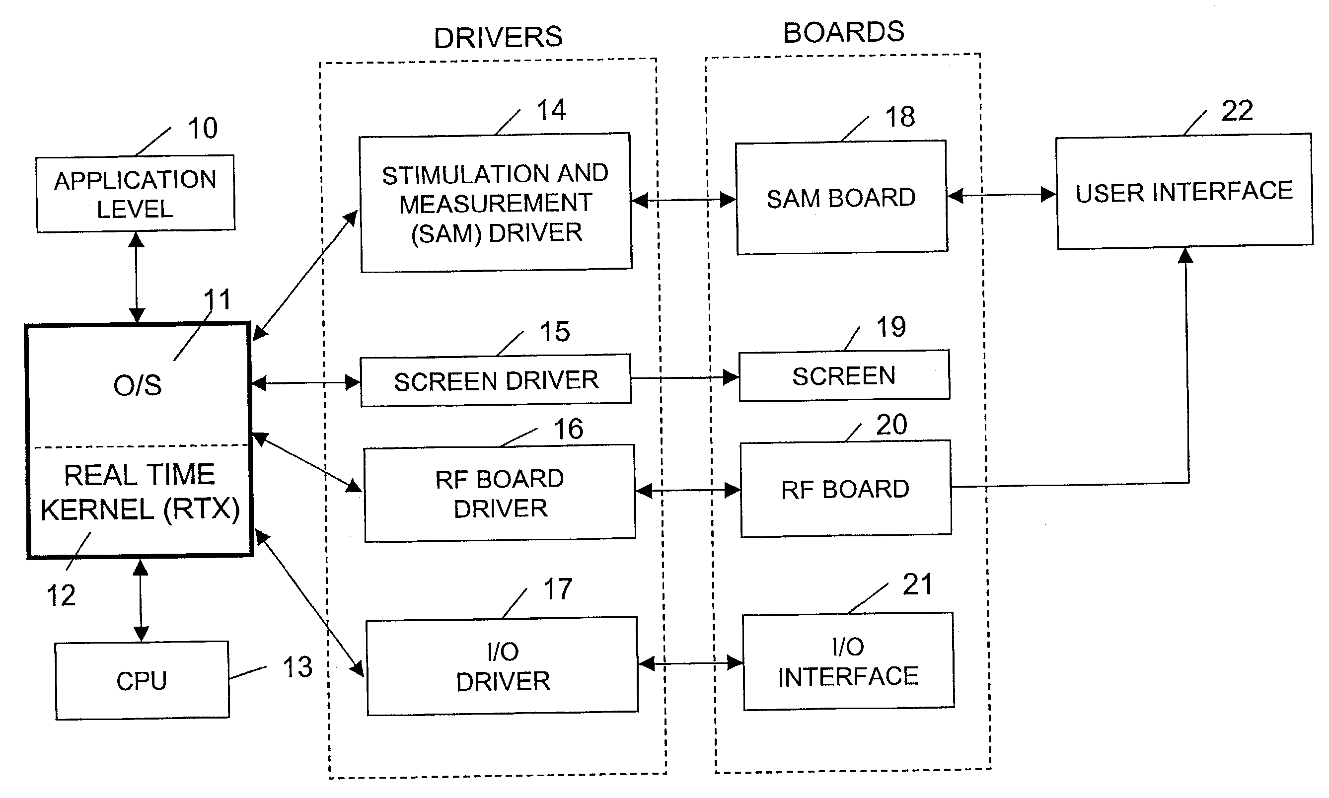
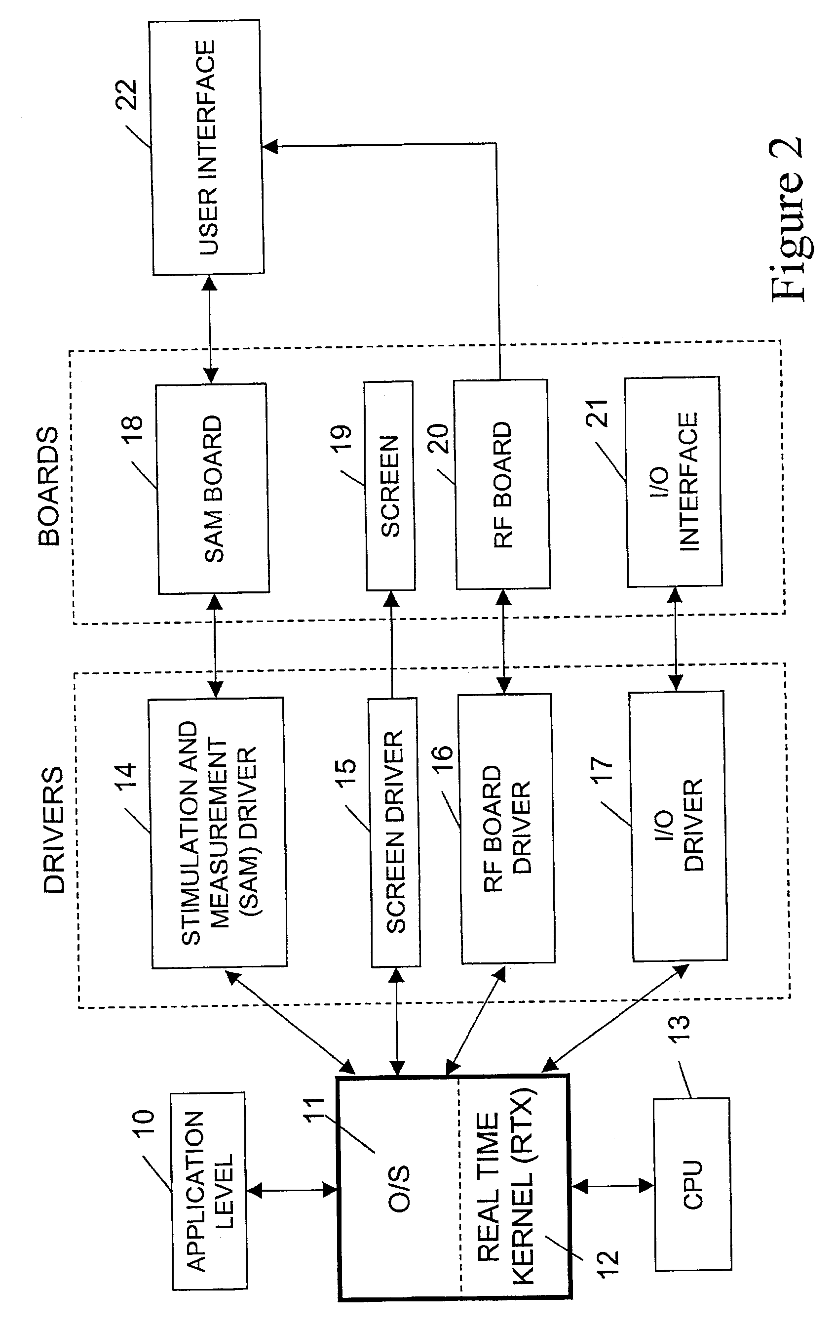
[0024] While illustrated in the block diagrams (FIGS. 2 and 3) as ensembles of discrete components communicating with each other via distinct data signal connections, it will be understood by those skilled in the art that the embodiments described herein are provided by a combination of hardware and software components, with some components being implemented by a given function or operation of a hardware or software system, and many of the data paths illustrated being implemented by data communication within a computer application or operating system. The structure illustrated is thus provided for efficiency of teaching the present embodiment.

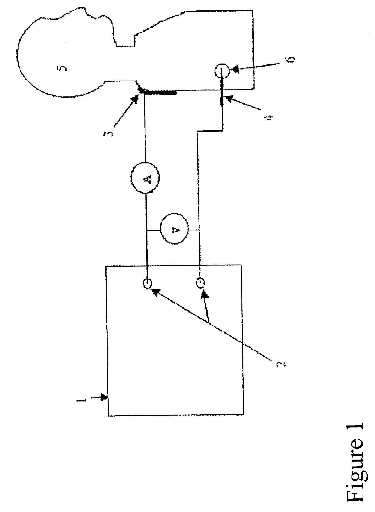
[0025] The signal generator has the ability to control the output and therefore the treatment in real time using a classical control system. In this case, the control system incorporates temperature feedback to adjust the level of current and voltage supplied to the tissue. Input to the control system is provided from the tissue temperature me...


PUM


Abstract

The invention relates to a medical probe signal generator. More particularly, it relates to a medical probe signal generator architecture. The present invention further relates to a system including a medical probe signal generator having an automatic probe type detector for detecting an identifier and at least one instrument cable comprising the identifier.

Description

CROSS REFERENCES TO RELATED APPLICATIONS [0001] This application is a continuation of U.S. patent application Ser. No. 10 / 122,413, filed on Apr. 16, 2002, which is incorporated herein by reference in its entirety.FIELD OF THE INVENTION [0002] The invention relates generally to an energy generator. More particularly, the invention relates to an apparatus for providing a controlled source of energy to an application tool, combining features that customize the utilization to a particular specialization. BACKGROUND OF THE INVENTION [0003] Electrical signal generators are used in a variety of medical applications. Examples include electrosurgery, tissue ablation, tissue perforation, neural stimulation, and neural lesioning. Neural lesion procedures using electrical current with a high frequency wave, typically in the radiofrequency (RF) spectrum, have been in use since the early 1950s. Among a variety of therapeutic purposes, the application of RF in the nervous system is commonly used i...

Claims


Application Information

Patent Timeline
Patent Type & Authority Applications(United States)
IPC IPC(8): A61B18/18
CPCA61B18/1206A61B2018/00988A61B2018/00791A61B2018/00702A61B90/98A61B2018/00875
Inventor SHAH, KRISHANBAYLIS, FRANK HEADLEY
Owner AVENT INC
Why Eureka
Try Eureka