
Mechanism for assembly of ultrasonic instrument

a technology of ultrasonic instruments and assembly methods, which is applied in the field of ultrasonic surgical clamps and coagulator apparatus, can solve the problems of insufficient proximal loading of end-effectors or blade tips, tissue tags, and insufficient activity of proximal blades

Active Publication Date: 2007-12-06
CILAG GMBH INT
View PDF33 Cites 163 Cited by
  • Summary
  • Abstract
  • Description
  • Claims
  • Application Information

AI Technical Summary

Benefits of technology

[0083]Several benefits and advantages obtain from one or more of the expressions of the invention. Having a tissue pad with a base material and at-least-one pad insert material allows the base material and the at-least-one pad insert material to be chosen with a different hardness, stiffness, lubricity, dynamic coefficient of friction, heat transfer coefficient, abradability, heat deflection temperature, glass transition temperature and / or melt temperature to improve the wearability of the tissue pad, which is important when high clamping forces are employed because tissue pads wear faster at higher clamping forces than at lower clamping forces. Further benefits and expressions of this embodiment are disclosed in U.S. patent application Ser. No. 11 / 065,378, filed on Feb. 24, 2005 and commonly assigned to the assignee of the present application.

Problems solved by technology

Some current ultrasonic shears devices, however, have the tendency to create tissue tags.
Tissue tags may result from insufficient end-effector or blade tip proximal loading and / or lower proximal blade activity.
This presents certain problems in terms of the pressure profile exerted on the tissue.
Additionally, the fact that blade amplitude decreases moving proximal of the tip of the blade makes the situation worse since the amount of energy transferred to the tissue, even if the pressure was constant, is reduced.
Although these designs have been adequate, they tend to suffer from longevity issues since the pads tend to deteriorate over long surgical procedures.
Additionally, newer designs of clamp coagulator shears increase blade amplitude and / or the loading of the pad against the tissue and blade and overwhelm the pad material, resulting in less than required tissue pad life.
The pad material limits the amount of force that may be applied against the tissue and blade, which in turn limits the tissue thickness or vessel size that some current clamp coagulator shears may effectively cut and coagulate.
Current composite pads may be difficult or expensive to manufacture.
Some current designs of clamp coagulator ultrasonic shears are limited in the length of the active blade available for use by surgeons due to inherent limitations in the effective transfer of mechanical motion along the longitudinal path of the blade from the transducer assembly.
Although new blade geometry has mitigated some of these problems, longer active blade lengths, or blades that have more mass (created by larger diameter or larger lengths) have a tendency to shrink the frequency window between resonant and anti-resonant frequencies making it difficult or impossible for ultrasonic generators to lock on to the proper frequency to drive the waveguide, blade and transducer assembly.
Many problems, however, are inherent with rigid node supports.
Materials such as thermoset polymers that are capable of withstanding the pressure and temperature requirements of an ultrasonic blade node support are often too expensive to be utilized in production.
The use of thermoplastics would improve manufacturability from a cost perspective but may not hold up to the pressure and temperature requirements of an ultrasonic blade node support.
In applications with high clamp forces, however, the difference in force attributable to the slope over the possible range of spring compressions becomes very significant and may exceed the maximum force allowable in the blade, in the tube assemblies or in other components of the system.
If this occurs, the blade may bend, the actuation mechanism may fail or undesirable tissue effects may occur (i.e. fast cutting, but minimal tissue coagulation).
In some cases, though, the surgeon may, unknowingly, fail to apply the full force of the jaw against the tissue resulting in incomplete tissue cuts or insufficient coagulation.
Alternatively, the surgeon may unknowingly open the clamp arm during a transection that results in incomplete tissue cuts or insufficient coagulation.
Key drawbacks with this type of instrument activation include the loss of surgeon focus on the surgical field while the surgeon searches for the foot pedal, the foot pedal gets in the way of the surgeon's movement during a procedure and surgeon leg fatigue during long cases.
A multi-piece assembly is more costly in that separate pieces have to be molded and then assembled.
In addition, the pieces have a tendency to wear rapidly leading to failure of the wrench.

Method used


Image

  • Mechanism for assembly of ultrasonic instrument
  • Mechanism for assembly of ultrasonic instrument
  • Mechanism for assembly of ultrasonic instrument

Examples


Embodiment Construction

[0050]Before explaining the present invention in detail, it should be noted that the invention is not limited in its application or use to the details of construction and arrangement of parts illustrated in the accompanying drawings and description. The illustrative embodiments of the invention may be implemented or incorporated in other embodiments, variations and modifications, and may be practiced or carried out in various ways. Further, unless otherwise indicated, the terms and expressions employed herein have been chosen for the purpose of describing the illustrative embodiments of the present invention for the convenience of the reader and are not for the purpose of limiting the invention.

[0051]Further, it is understood that any one or more of the following-described embodiments, expressions of embodiments, examples, etc. can be combined with any one or more of the other following-described embodiments, expressions of embodiments, examples, etc.

[0052]The present invention is p...


PUM


Abstract

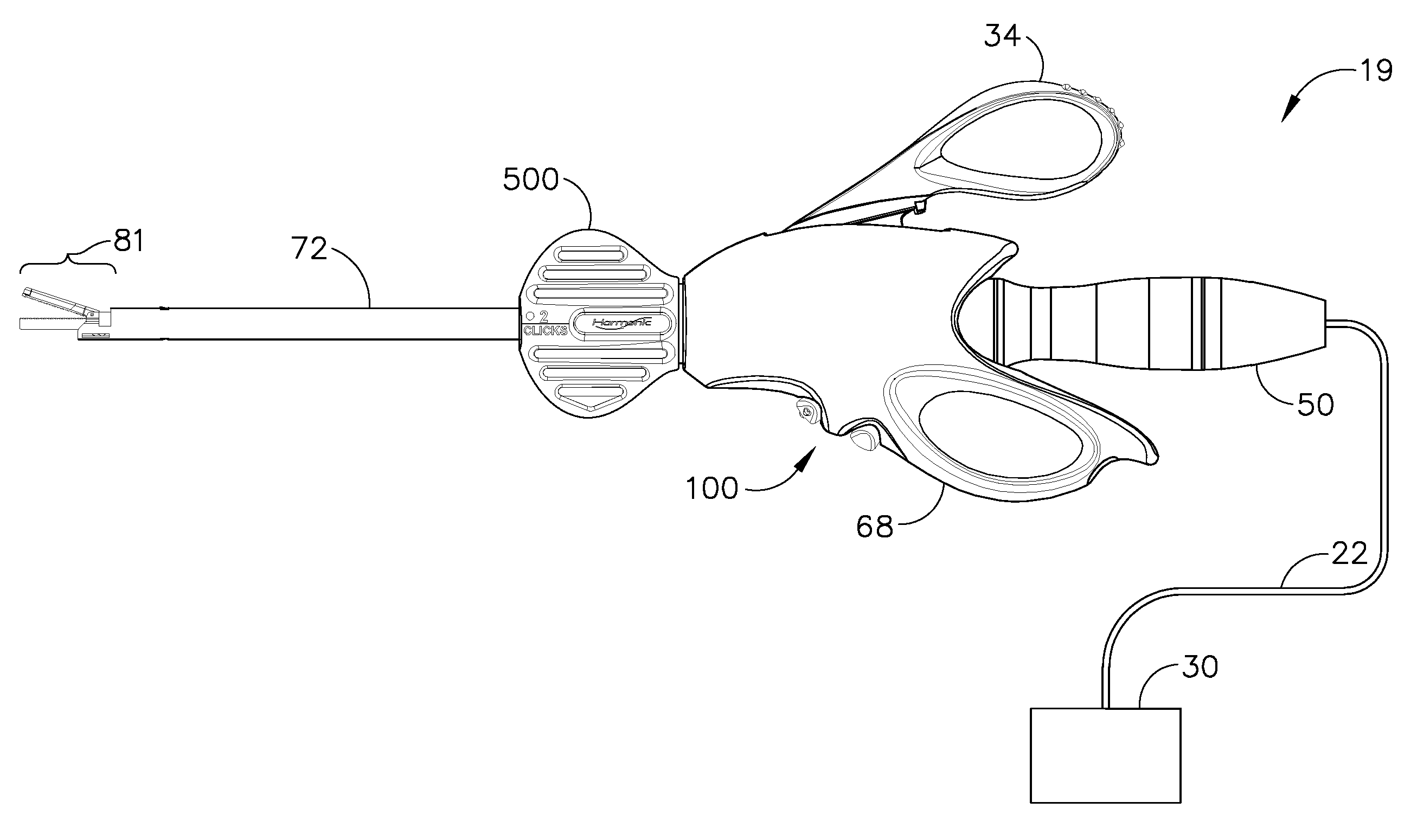
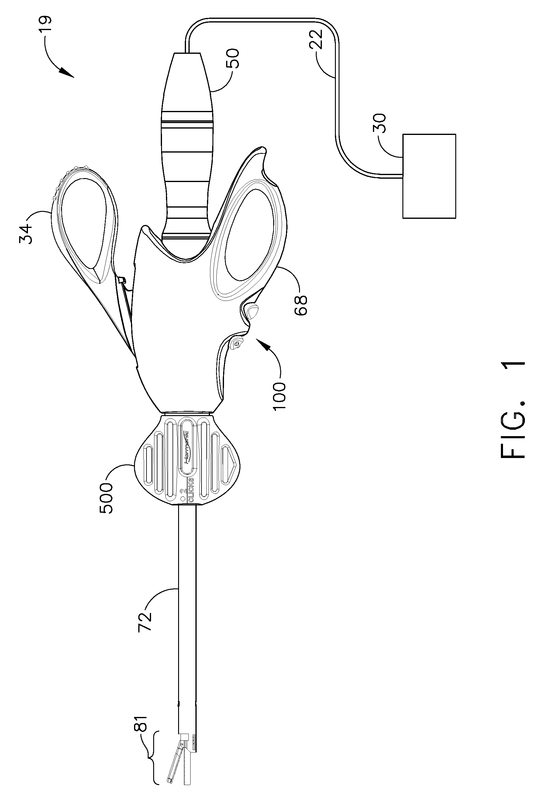
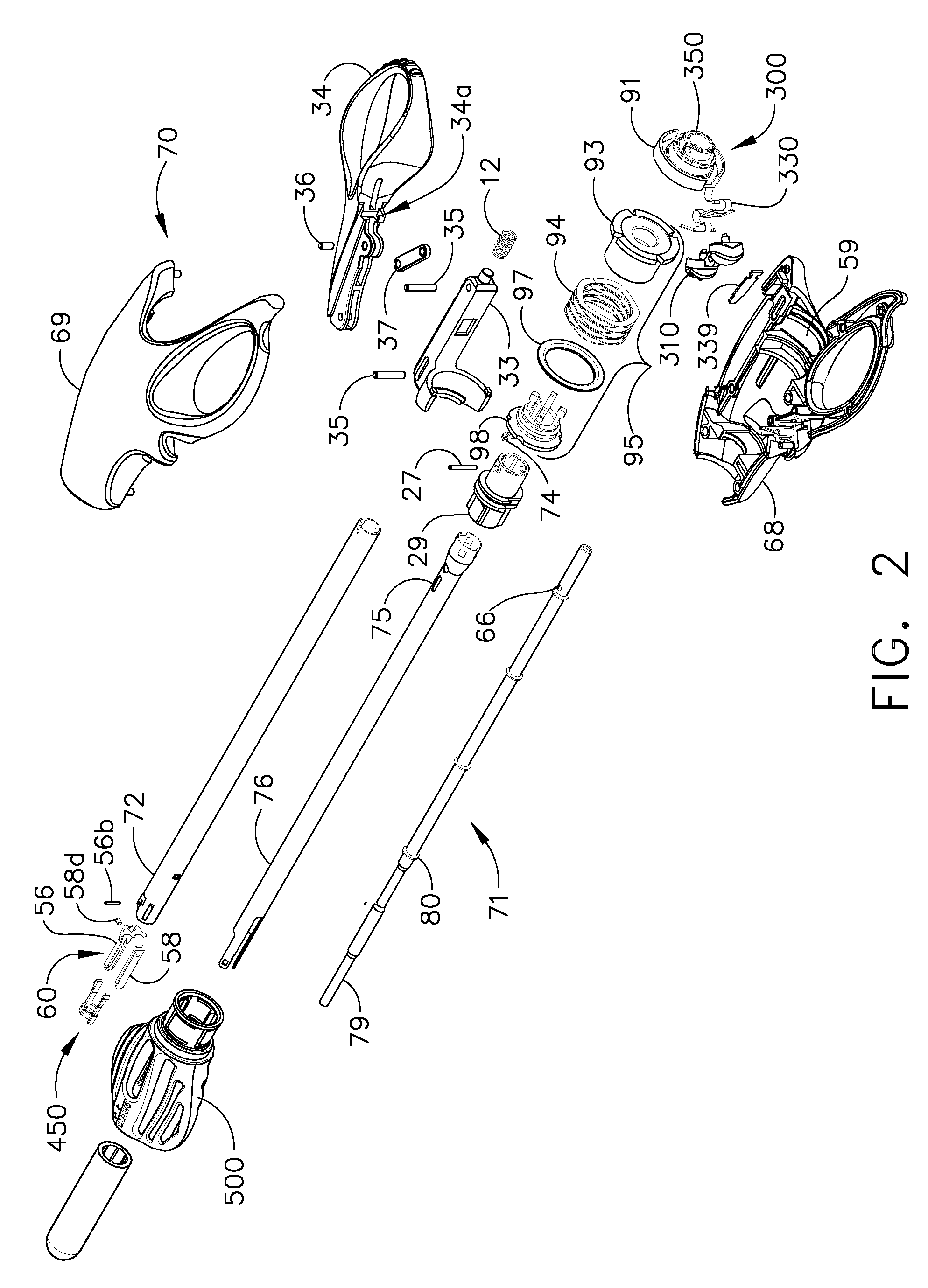
An ultrasonic clamp coagulator system that is configured to permit selective cutting, coagulation and clamping of tissue during surgical procedures. An elongated portion of the instrument can be configured for endoscopic applications and has an outside diameter of less than 6 mm. The system includes a one-piece torque wrench that is provided with cantilever arms aligned in an annular fashion about the centerline of the torque wrench. The cantilever arms include teeth in an inward perpendicular fashion in relation to cantilever arms. The clamp coagulator includes an outer tube retainer that includes spline gears projecting in a perpendicular fashion along the outer circumference of retainer. Torque is transmitted through the cantilever arms to the spline gears for attaching a handpiece to the clamp coagulator.

Description

REFERENCE TO RELATED APPLICATIONS [0001]The present application claims the priority benefit of U.S. provisional patent application Ser. No. 60 / 809,971, filed on Jun. 1, 2006.FIELD OF THE INVENTION [0002]The present invention relates, in general, to ultrasonic surgical instruments and, more particularly, to an ultrasonic surgical clamp coagulator apparatus particularly configured to provide increased tissue transection forces.BACKGROUND OF THE INVENTION [0003]This application contains subject matter that relates to and incorporates by reference in their entirety, for any and all purposes, the following non-provisional applications:[0004]ULTRASONIC SURGICAL BLADE AND INSTRUMENT HAVING A GAIN STEP, U.S. Pat. No. 7,163,548.[0005]TISSUE PAD FOR USE WITH AN ULTRASONIC SURGICAL INSTRUMENT, U.S. Ser. No. 11 / 245,819, filed Oct. 7, 2005;[0006]COMBINATION TISSUE PAD FOR USE WITH AN ULTRASONIC SURGICAL INSTRUMENT, U.S. Ser. No. 11 / 246,794, filed Oct. 7, 2005;[0007]ACTUATION MECHANISM FOR USE WI...

Claims


Application Information

Patent Timeline
IPC IPC(8): A61B18/18
CPCA61B17/320092A61B2090/033A61B2017/2825G10K11/24A61B2090/031A61B2017/320071A61B2017/320093A61B2017/320089A61B2017/320094A61B2017/320095B25B23/142
Inventor YOUNG, JOSEPH E.WITT, DAVID A.FORTSON, REGINALD D.ADAMS, THOMAS E.WEED, JOHN A.DANNAHER, WILLIAM D.
Owner CILAG GMBH INT
Learn More