Compact modular CPU cooling unit

a cooling unit and modular technology, applied in indirect heat exchangers, lighting and heating devices, instruments, etc., can solve the problems of not being particularly compact in their overall configuration, and achieve the effects of improving air flow efficiency, superior compactness and utilization of space, and saving spa

Active Publication Date: 2007-12-13
COOLIT SYSTEMS INC
View PDF11 Cites 16 Cited by
  • Summary
  • Abstract
  • Description
  • Claims
  • Application Information

AI Technical Summary

Benefits of technology

[0004]The subject invention incorporates the cold plate, air to liquid heat exchanger, liquid pump, and associated hoses and fittings into a self contained, modular unit, with superior compactness and utilization of space. A modular unit can be easily attached to each of any number of CPU's within a computer case, with no modification to the case itself. The components cooperate within the modular unit not only to save space, but to create an improved and efficient air flow over the air to liquid heat exchanger.

Problems solved by technology

As production CPUs have begun to approach the same speeds, the liquid pumps, heat exchangers and fan units have generally been designed into the computer case initially, but are still separate components, not particularly compact in their overall configuration, and generally operating essentially independently.

Method used


Image

  • Compact modular CPU cooling unit
  • Compact modular CPU cooling unit
  • Compact modular CPU cooling unit

Examples


Embodiment Construction

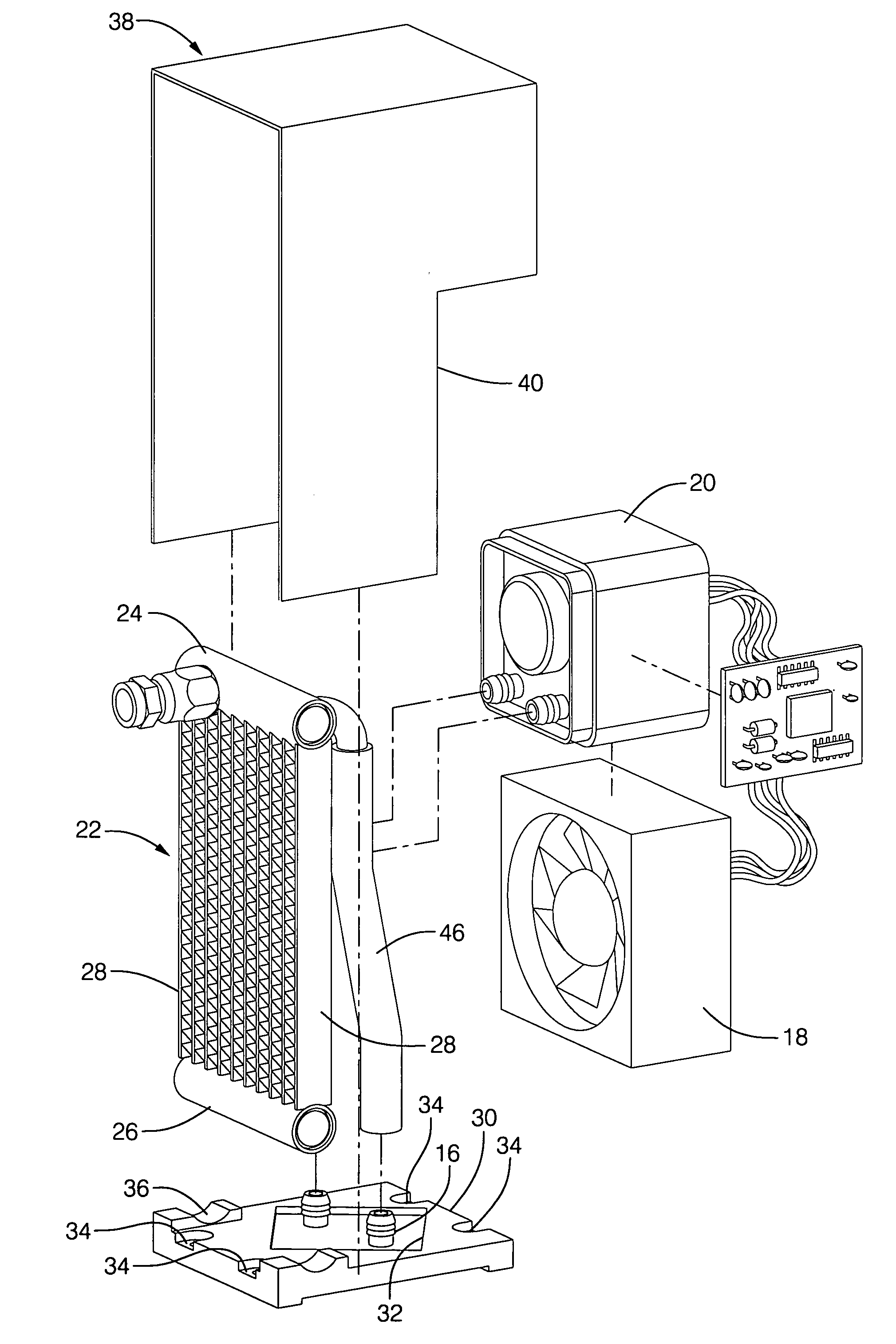
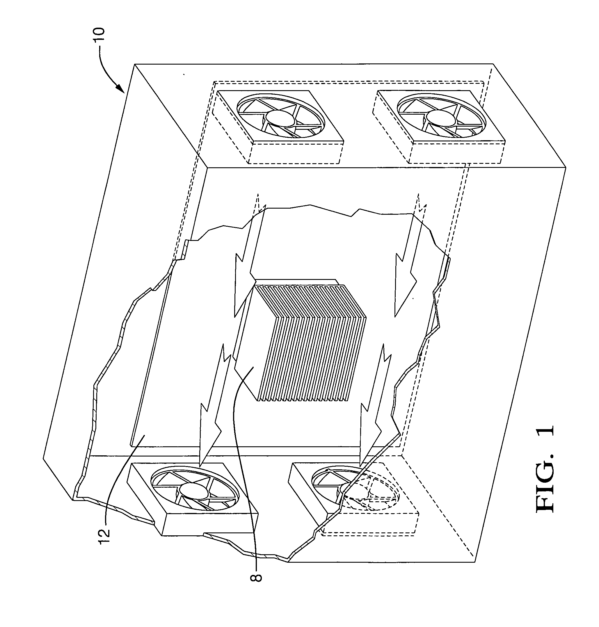
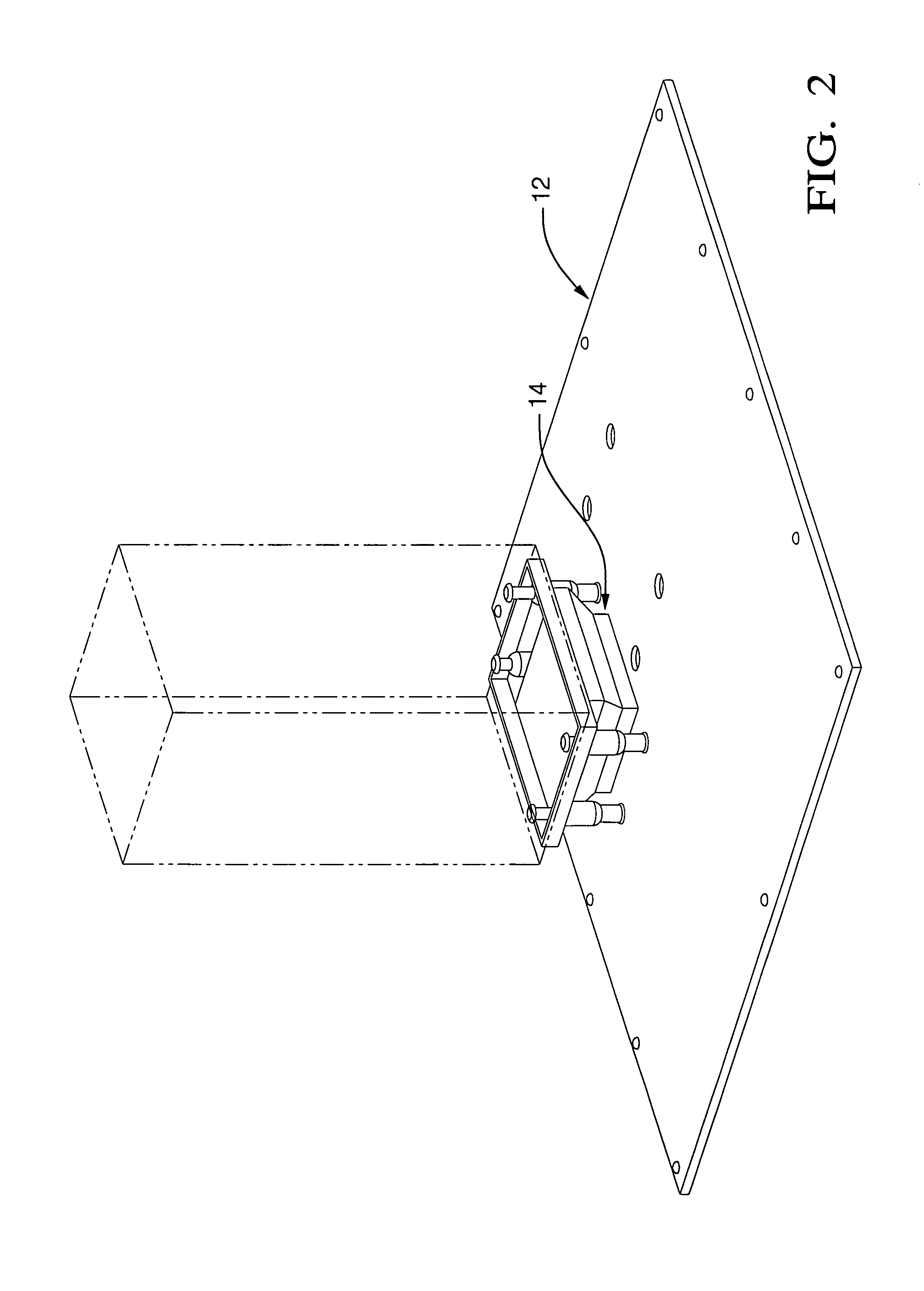
[0013]Referring first to FIGS. 1 and 2, the outline of a computer case 10 is shown, essentially a box with a floor in the form of a main or “mother” board 12 to which numerous circuit boards and other components would be fixed, including a CPU as described above, the location of which is indicated generally at 14. Case 10 typically has several pusher and puller fans around its perimeter, as well as screened air inlets and outlets, which continually supply a forced flow of outside air into and out of case 10 to air cool the components inside the box. This pre existing air stream is indicated by the arrows. This internal air flow is used to advantage by the cooling module of the invention, as described below. The cooling of CPU 14 has been typically assisted by a finned heat sink 8 thermally bonded to and clamped to the CPU upper surface, with the fins being exposed to the general air stream within the case 10 itself, similarly to any other heat producing component within the case 10....


PUM


Abstract

A modular CPU cooling unit designed to fit within the available space within an existing box or cabinet containing a CPU. The fan, pump and liquid to air cross flow heat exchanger are fitted within the available volume with the fan spaced away from the heat exchanger a suitable distance to pull air through the entire face area of the heat exchanger, even though it is considerably larger than the fan.

Description

TECHNICAL FIELD[0001]This invention relates to electronic cooling assemblies in general, and specifically to a self contained, compact and modular cooling unit for a CPU or similar heat producing electronic component.BACKGROUND OF THE INVENTION[0002]Increasingly powerful electronic components, such as computer chips or central processing units (CPUs), produce higher wattages of waste heat, which must be continually removed in order to allow the component to operate efficiently. Generally, one planar surface of such a component is exposed, usually indirectly exposed through a thin cover or “lid,” and heat is extracted by some type of add on cooling assembly that is thermally bonded to the exposed surface. Early on, a relatively simple so called “heat sink,” generally a metal plate with cooling fins, was bonded to the exposed surface of the component, and a fan mounted somewhere on or inside the computer case forced air over the cooling fins and out of the case. This worked sufficient...

Claims


Application Information

Patent Timeline
Patent Type & Authority Applications(United States)
IPC IPC(8): F28F13/12
CPCG06F1/20
Inventor PAWLAK, JOHN LAWRENCEREYZIN, ILYABHATTI, MOHINDER SINGH
Owner COOLIT SYSTEMS INC
Why Eureka
Try Eureka