Optical Component and Backlight Unit Using the Optical Component

a technology of optical components and backlight units, applied in waveguides, lighting and heating apparatuses, instruments, etc., can solve the problems of narrow viewing angle and noticeable screen flaws, and achieve the effects of high illumination, suitably increased diffusion of light in a target direction, and suitably suppressed diffusion in other directions

Inactive Publication Date: 2007-12-13
SAKARI +1
View PDF0 Cites 30 Cited by
  • Summary
  • Abstract
  • Description
  • Claims
  • Application Information

AI Technical Summary

Benefits of technology

[0067] In the optical sheet according to the present invention, the diffusion of light in a target direction can be suitably increased, and the diffusion in other directions can be suitably suppressed. As a result, a high-quality image having high-luminance, a wide viewing angle, and inconspicuous flaws can be acquired.
[0068] Furthermore, in the optical sheet according to the present invention, a favorable anisotropic diffusion light can be acquired by the irregular lens rows. As a result, a higher quality image can be acquired.
[0069] Still further, in the optical sheet according to the present invention, a more favorable anisotropic diffusion light can be acquired by the array direction of the lens rows differing with the incident surface and the light-exiting surface. As a result, a higher quality image can be acquired.
[0070] Still further, in the optical sheet according to the present invention, the anisotropic diffusion light can be acquired with further certainty because the lens rows are random and nonconsecutive prism rows. As a result, a higher quality image can be acquired.
[0071] Still further, in the optical sheet according to the present invention, transfer performed when an optical sheet is formed is improved, and flaws such as scratches made during assembly can be reduced. As a result, a higher quality image can be acquired.
[0072] Still further, in the optical sheet according to the present invention, a favorable anisotropic diffusion light can be acquired by the optical sheet serving as the optical component. As a result, a higher quality image can be acquired.

Problems solved by technology

At the same time, as described above, problems occur in that the viewing angle becomes narrow and flaws in the screen become noticeable when the luminance is increased.

Method used


Image

  • Optical Component and Backlight Unit Using the Optical Component
  • Optical Component and Backlight Unit Using the Optical Component
  • Optical Component and Backlight Unit Using the Optical Component

Examples


first example

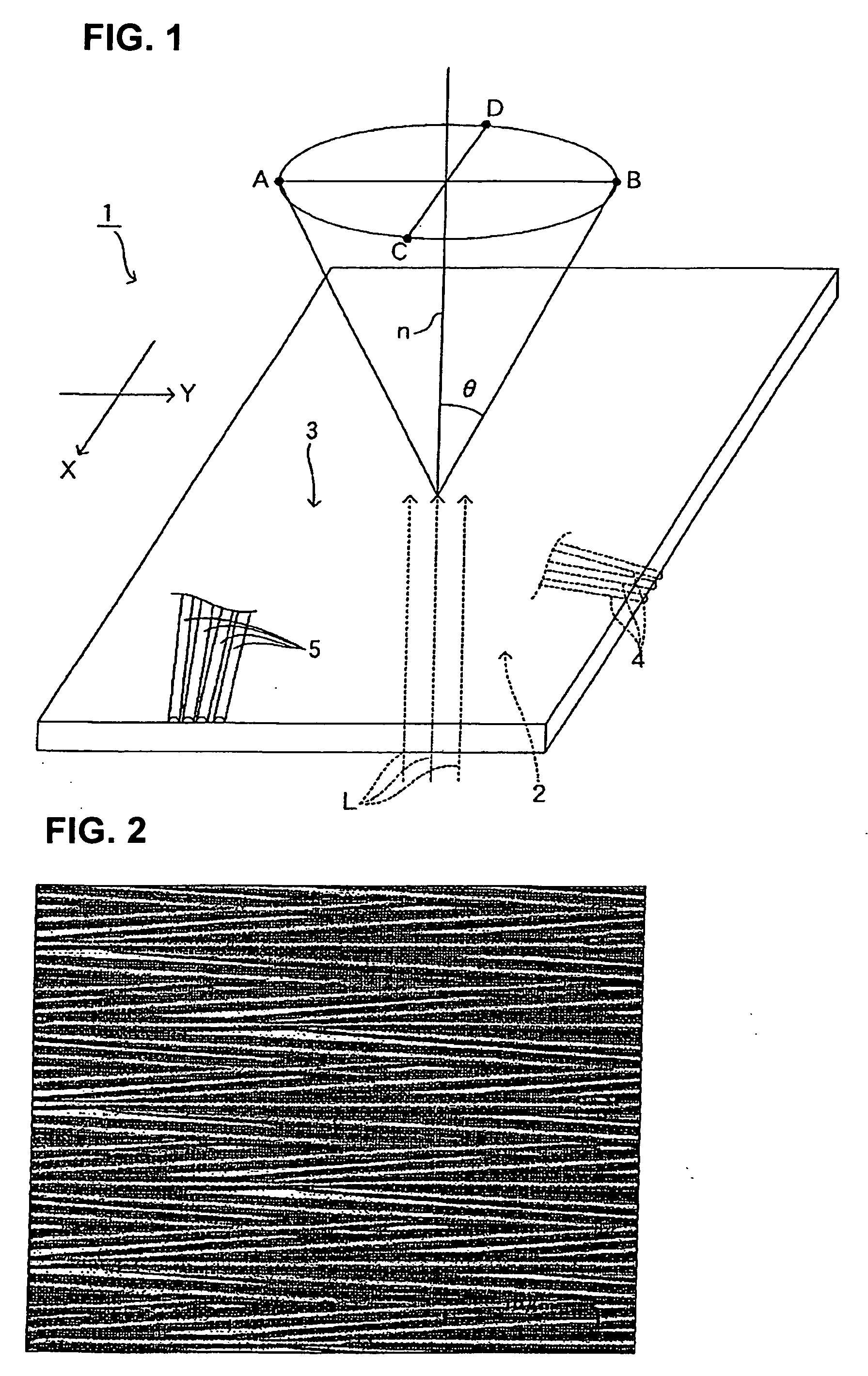
[0138] In the present example, a cutting process is performed on a metallic mold surface. The front surface of the metallic mold is a mirror-finished surface. The cutting processing is performed by an alternated use of three types of diamond bites. The respective apex angles of the diamond bites are 45°, 60°, and 75°. All of the diamond bites have an arc-shaped curved surface of which the tip apex section has a radius of 2 μm.

[0139] At this time, an NC processing machine is set so as to change the direction of one direction between an angle of −20° and 20° and change the length of the cut from the bite between 10μ and 100μ.

[0140] The metallic mold, formed as such, is heat-pressed into a 2 mm-thick acrylic resin board serving as the base material, thereby transferring the shape of the metallic mold to the acrylic resin board.

[0141] As a result, a diffusion sheet in which irregular lens rows are formed on the resin board surface is acquired as the optical component.

[0142] In addit...

example 1

Comparison Example 1

[0147] As shown in Table 1, the diffusion sheet that is the optical component in the present example has a higher luminance than the comparison example. It is clear that the diffusion sheet is optimal for the backlight unit of the liquid crystal display device.

[0148] The optical component 1 according to the present invention is not limited to the diffusion sheet. A favorable anisotropic diffusion light can be acquired even when the optical component 1 is used on the light-guiding board or the prism sheet in the backlight unit.

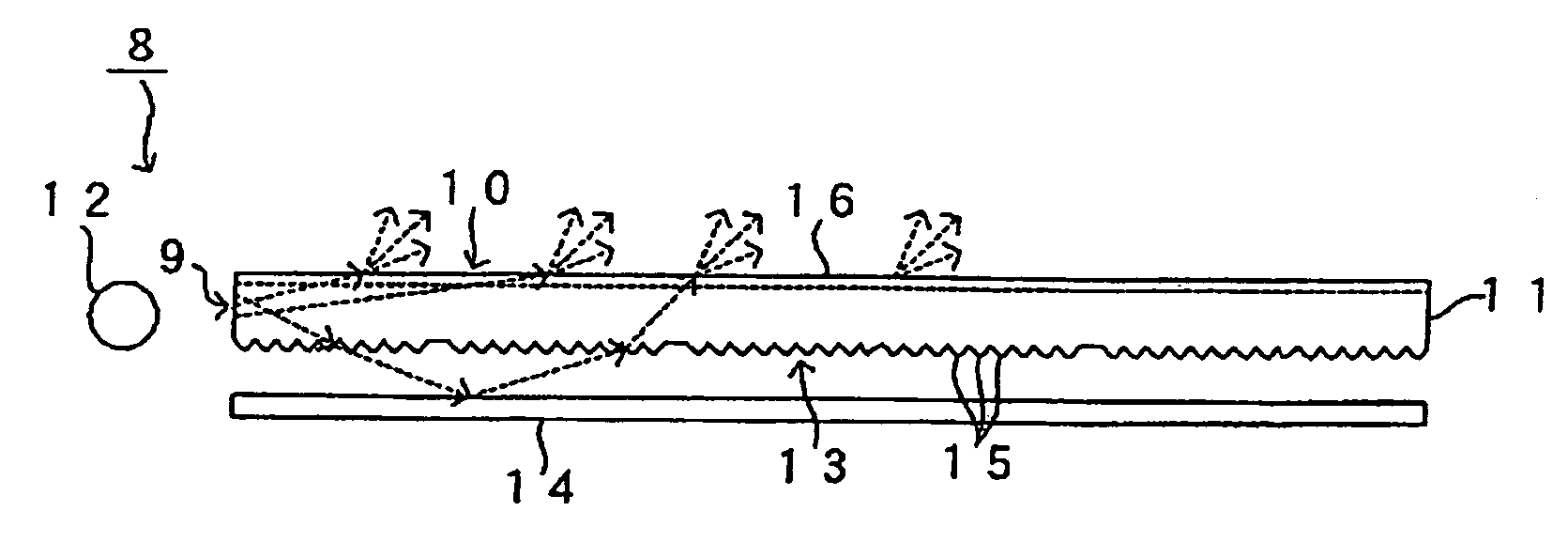
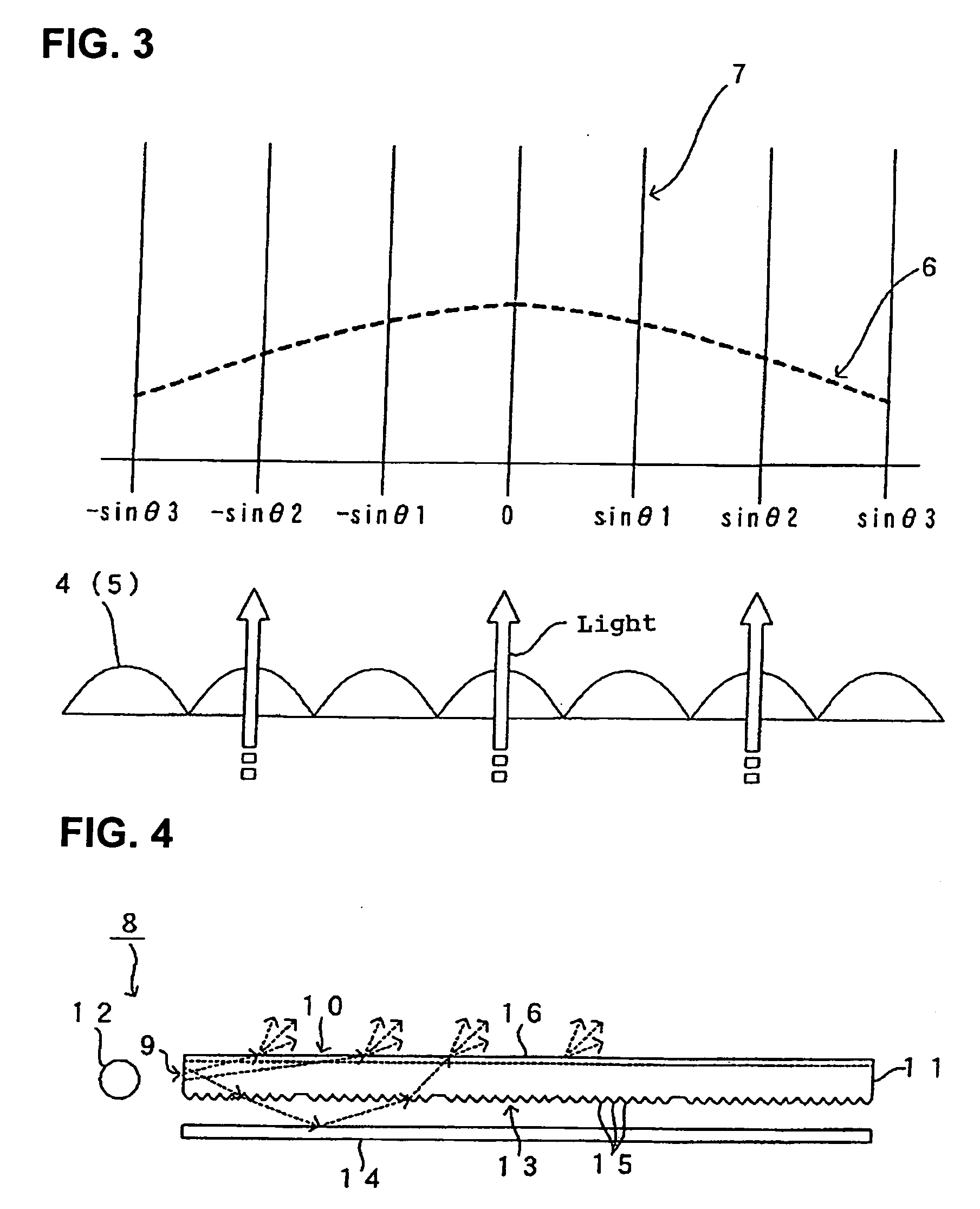
[0149] Next, an embodiment of the backlight unit according to the present invention will be explained with reference to FIG. 4 and FIG. 5.

[0150] As shown in FIG. 4, a backlight unit 8 according to the present embodiment has a light-guiding board 11 serving as the optical component. The light-guiding board 11 includes an incident surface 9 and a light-exiting surface 10 that is perpendicular to the incident surface 9. A light source 12 is...


PUM


Abstract

[PROBLEMS] An optical component in which the viewing angle can be widened while sustaining a high luminance and the defect of a display can be made inconspicuous, and a backlight employing the optical component.
[MEANS FOR SOLVING PROBLEMS] When a substantially collimated light impinges on the plane of incidence (9), an outgoing light from the outgoing plane (10) exhibits anisotropy in its intensity along an azimuth of 30° to normal to the outgoing plane (10), the anisotropy being such that the ratio between a highest intensity and a lowest intensity in the intensity distribution of outgoing light intensity along the azimuth of 30° is set to not smaller than 1.2.

Description

BACKGROUND OF THE INVENTION [0001] 1. Field of the Invention [0002] The present invention relates to an optical component and a backlight unit using the optical component. In particular, the present invention relates to an optical sheet suitable for use in an image display device, such as a backlight unit of a liquid crystal display device, a projector screen, or a plasma display, and a backlight unit using the optical sheet. [0003] 2. Description of the Related Art [0004] Conventionally, technology for controlling light has been applied in various fields and has become a useful part of our lives. In particular, screens that are large, as well as having high-definition, high-luminance, and high-quality, are being developed for image display devices. [0005] Various optical components are implemented for the purpose of enhancing the luminance, widening the viewing angle, and improving the screen quality of the backlight unit of liquid crystal display devices, plasma displays, and proj...

Claims


Application Information

Patent Timeline
Patent Type & Authority Applications(United States)
IPC IPC(8): F21V8/00F21V7/10G02B5/02G02B5/04
CPCG02B5/0221G02B5/0257G02F1/133606G02B6/0033G02B5/0278Y10S385/901G02F1/1335
Inventor ISHIHARA, SEIICHIOKADA, TAKASHI
Owner SAKARI
Why Eureka
Try Eureka