
Methods of forming solder connections and structure thereof

a technology of solder connection and semiconductor device, which is applied in the direction of semiconductor devices, electrical appliances, basic electric elements, etc., can solve the problems of reducing the potential integrity of bump attachment, affecting device performance and reliability, and causing the disruption of solder connection. to achieve the effect of preventing the disruption of the solder connection

Inactive Publication Date: 2007-12-13
IBM CORP
View PDF8 Cites 36 Cited by
  • Summary
  • Abstract
  • Description
  • Claims
  • Application Information

AI Technical Summary

Benefits of technology

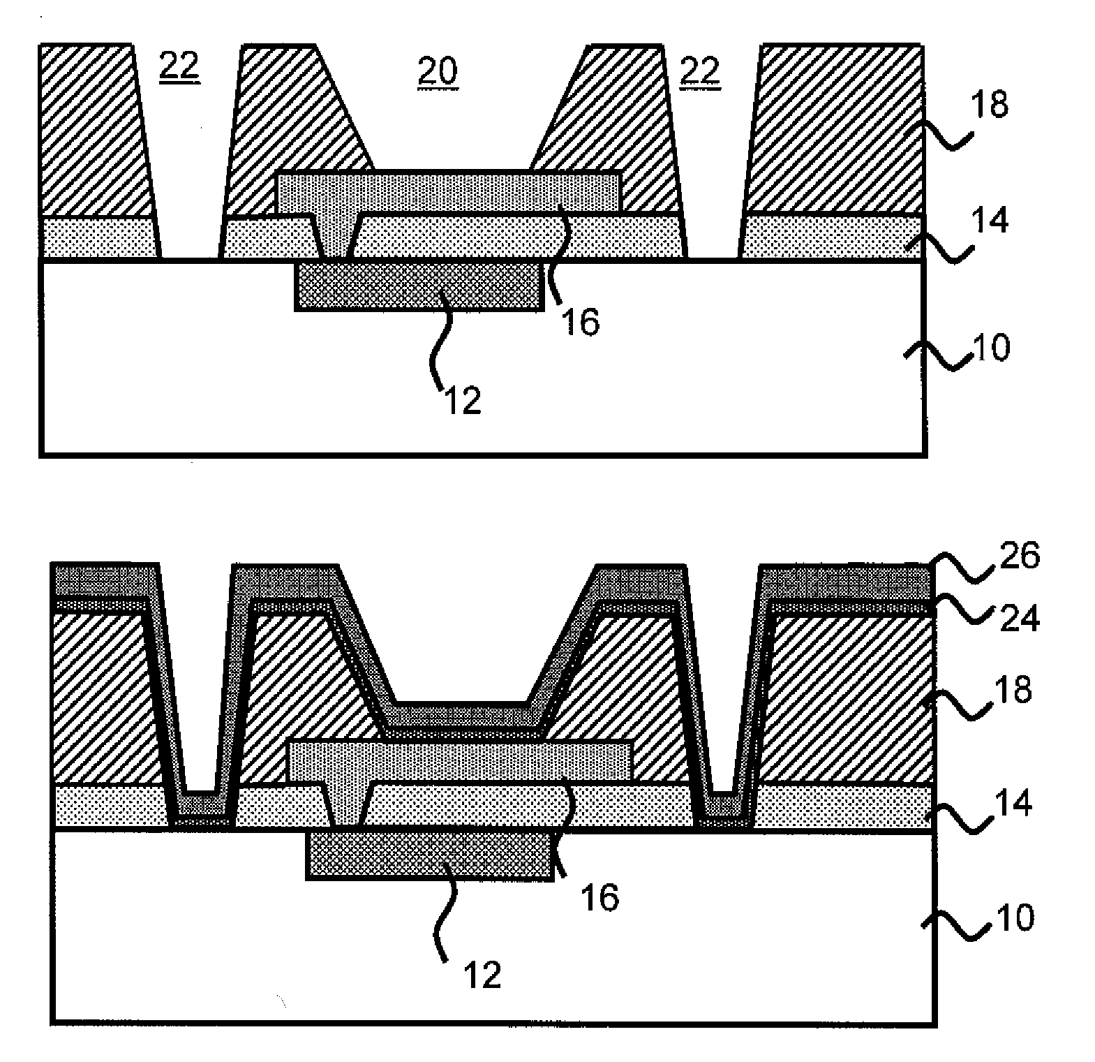
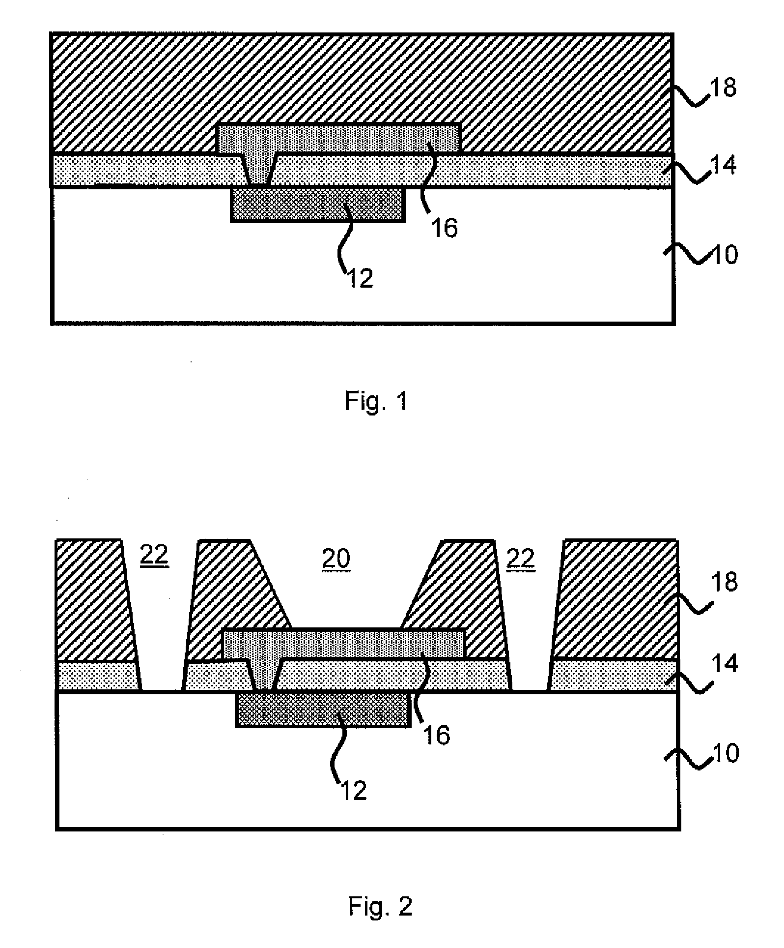
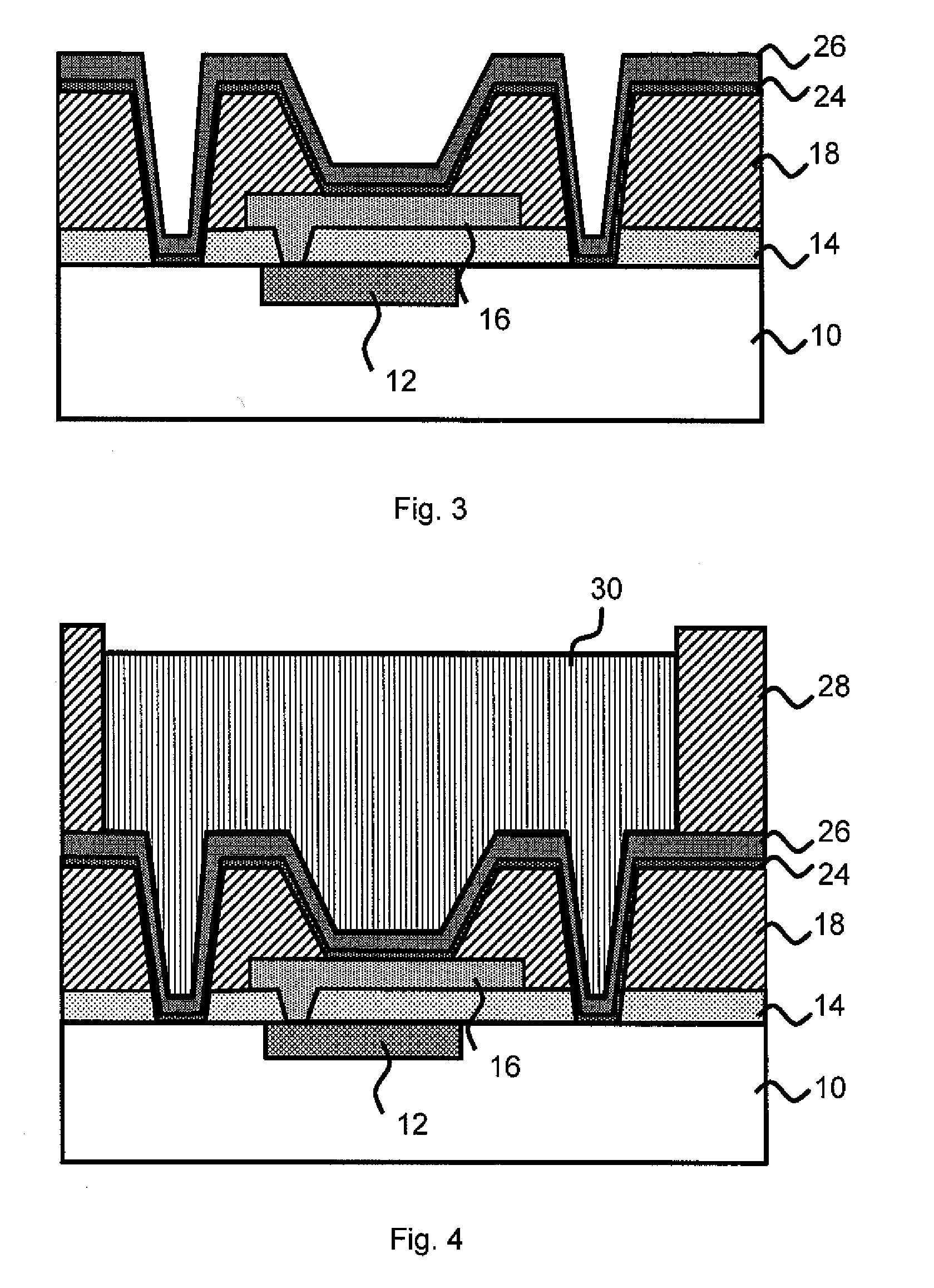
[0008]In a second aspect of the invention, a method includes forming a passivated layer with dummy vias on at least one side of a well positioned over at least one metallized layer in a structure. The method further includes forming a BLM layer in the dummy vias and the well and placing solder material over the BLM layer. The solder material is flowed to form a solder bump of solder material. The dummy vias increase a surface contact area for the solder material.
[0009]In an aspect of the invention, a controlled collapse chip connection (C4) structure is provided. The structure includes one or more dummy vias adjacent to the well of the solder connection. The dummy vias intercept stress related to cracks and prevent solder connection disruptions.
[0010]In another aspect of the invention, a semiconductor structure including a solder bump is provided. The solder bump has incorporated BLM material over a metallized structure that includes a dummy via. The dummy via has side walls and increase the surface contact area of the BLM material. The BLM material is at least partially formed in the dummy via.

Problems solved by technology

When the copper and underlying films are wet-etched (using the solder bump and / or or the Ni barrier layer as etch mask), there rises the problem of under bump removal or undercut.
This, in turn, reduces the potential integrity of bump attachment.
In such case, as the C4 pitch becomes smaller, process control becomes even more critical with respect to the reliability and utility of the final C4 structure since a relatively consistent undercut per edge represents a greater threat to the integrity of the final overall C4 structure.
Also, it should be understood that as semiconductor devices become smaller, a point is reached where a 10 μm undercut is not acceptable and will significantly degrade device performance and reliability.

Method used


Image

  • Methods of forming solder connections and structure thereof
  • Methods of forming solder connections and structure thereof
  • Methods of forming solder connections and structure thereof

Examples


Embodiment Construction

[0014]The invention relates to methods for forming solder connections on a semiconductor device. In embodiments, the methods of the invention reduce, if not entirely eliminates, corrosion or undercut of underlying layers of the solder connection. The present invention further increases surface area contract between the structure and the solder material, while eliminating or substantially reducing the effects of cracking or the propagation of cracks. In this manner, the solder bump prepared by the present method supports an increased device lifetime and performance.

[0015]In embodiments, the invention is a controlled collapse chip connection (C4) structure comprising a plurality of dummy vias adjacent to the well for a solder connection of a C4 structure. The plurality of dummy vias intercept stress related cracks to prevent solder connection disruptions.

[0016]FIG. 1 represents a beginning structure at the back-end-of-line process level. The structure includes a metallization layer 12...


PUM


Abstract

A method for forming solder connections using dummy vias and the device. The dummy vias are formed prior to the application of ball limiting metals or solder material. After placing the under ball materials and the solder materials, the material covering the dummy vias has an increased surface contact and thus provide improved robustness and lifetime of the solder connection. Structures of implementation of the method are provided with either completely or partially filled dummy vias.

Description

FIELD OF THE INVENTION[0001]The invention relates to methods of forming solder connections onto a semiconductor device and more particularly, methods of forming solder connections with increased surface area contact, eliminating undercut and cracking effects resulting in a more stable device, and a resulting device.BACKGROUND OF THE INVENTION[0002]A solder connection on a semiconductor device includes several metal containing materials, including the solder bump itself which usually comprises low melting metal alloys or metal mixtures based on tin or lead. Less obvious are the materials underneath the solder bump which bridge the conductive connection between the solder bump and the first metallization contact that is formed at the back end of line processes of a semiconductor device. These under bump materials (UBM) are also referred to as the ball limiting metallurgical (BLM) layers, since they form the foundation of the solder bump and the solder material holds only at the area w...

Claims


Application Information

Patent Timeline
IPC IPC(8): H01L21/44
CPCH01L24/11H01L24/12H01L2924/00013H01L2224/0401H01L2224/05018H01L2224/05022H01L2224/05557H01L2224/05558H01L2224/1147H01L2224/11912H01L2224/13006H01L2224/13021H01L2224/13022H01L2224/13099H01L2224/16H01L2924/01013H01L2924/01014H01L2924/01022H01L2924/01028H01L2924/01029H01L2924/0105H01L2924/01074H01L2924/01082H01L2924/01327H01L2924/014H01L2924/05042H01L24/05H01L2924/01024H01L2924/01033H01L2224/29099H01L2224/02126H01L2224/13018
Inventor DAUBENSPECK, TIMOTHY H.GAMBINO, JEFFREY P.MUZZY, CHRISTOPHER D.SANTER, WOLFGANG
Owner IBM CORP
Learn More