
Torsion Beam Suspension

a technology of twisting beam and suspension, which is applied in the direction of resilient suspension, interconnection systems, vehicle components, etc., can solve the problems of deformation of spindle support rigidity, deformation of thread precision, etc., and achieve good load transmission efficiency, reduce the burden on the welded part, and eliminate the influence of thermal distortion

Inactive Publication Date: 2007-12-20
F TECH INC
View PDF23 Cites 13 Cited by
  • Summary
  • Abstract
  • Description
  • Claims
  • Application Information

AI Technical Summary

Benefits of technology

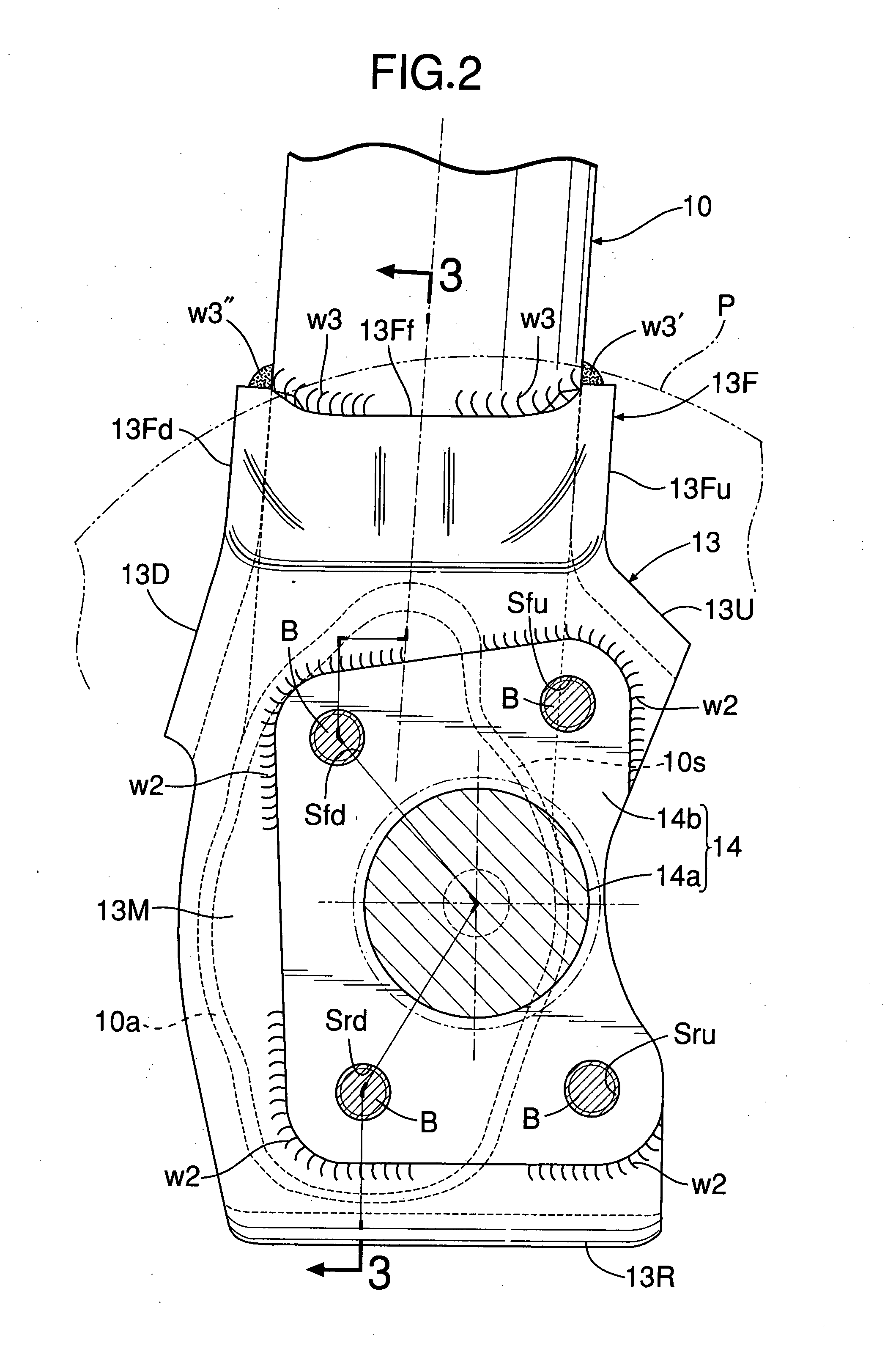
[0023] As hereinbefore described, in accordance with the aspects of the present invention, with regard to the torsion beam suspension in which the open end face at the rear end of the trailing arm is formed as a cut face that intersects the arm axis obliquely and this open end face is butt-welded to the plate main body of the spindle support plate, since the front bent flange extending forward along the outer face of the rear end part of the trailing arm and being welded to the outer face of the rear end part is provided integrally with the front end part of the plate main body of the spindle support plate, and the rear bent flange engaging with and being welded to the rear edge part of the trailing arm is provided integrally with the rear end part of the plate main body, even if the spindle support plate is formed so as to be thin, the rigidity of the front end part and rear end part of the plate main body can be enhanced effectively, thermal deformation of the plate main body due to thermal distortion when the arm open end is butt-welded thereto is suppressed effectively by the front and rear bent flanges, the area to which the arm open end is welded can be minimized, deformation of the seat face due to thermal distortion of the plate main body, which is made thin, is therefore suppressed effectively, and it is possible to ensure that there is precision flatness after welding, which is necessary for mounting the spindle base plate. In particular, since extending the front bent flange forward along the outer face of the rear end part of the trailing arm and welding its front edge to the arm outer face enables the spindle support plate to be welded to the trailing arm at a position as far forward as possible from the spindle axis, not only can the influence of thermal distortion be eliminated, but it is also possible to reduce the burden on the welded part as a result of good load transmission efficiency from the spindle support plate to the trailing arm, thereby improving the durability and increasing the strength.
[0024] Furthermore, in accordance with the first aspect of the present invention in particular, since the spindle base plate is superimposed on and fixed to the outer face of the plate main body and includes the four threaded hole portions at front, rear, upper, and lower positions with the spindle axis interposed therebetween, the four bolts for joining the brake related plate-shaped component to the spindle base plate being screwed into the four threaded hole portions, it is possible to handle an integral assembly of the trailing arm, the spindle support plate, and the spindle as a subassembly (small assembly), thus reducing the number of components and improving the efficiency of assembly of a vehicle. Furthermore, the above-mentioned bolt only needs to have a length that enables it to be screwed into the threaded hole portion of the spindle base plate in order to secure the brake related plate-shaped component; it is unnecessary to specially provide a weld nut on the reverse side of the spindle support plate, and the weight of the suspension can therefore be reduced by a corresponding amount.
[0025] Moreover, in accordance with the second aspect of the present invention in particular, since the plate main body includes the four threaded hole portions at front, rear, upper, and lower positions with the spindle axis interposed therebetween, four bolts for joining the spindle base plate or the brake related plate-shaped component to the plate main body being screwed into the four threaded hole portions, when it becomes necessary to replace either of the spindle or the brake related plate-shaped component, or the trailing arm due to wear, deformation, etc., only one thereof needs to be replaced, and the cost of replacement can be reduced by a corresponding amount.
[0026] Furthermore, in accordance with the third aspect of the present invention in particular, since at least one of the threaded hole portions is positioned outside the arm open end face, compared with a case in which four all threaded hole portions are contained inside the open end face of the arm rear end, the degrees of freedom in selecting the positions where the threaded hole portions are disposed are greatly increased and, moreover, even if some of the threaded hole portions are disposed outside the open end face of the arm, it is possible to easily ensure that there is sufficient support rigidity for the outside threaded hole portions by specially providing the above-mentioned front and rear bent flanges.
[0027] Moreover, in accordance with the fourth aspect of the present invention in particular, since the front bent flange is formed so as to have a substantially U-shaped cross-section by integrating the front flange portion, the upper flange portion, and the lower flange portion and butt-welding them to the outer face, upper face, and lower face of the arm rear end part respectively, the arm rear end part is supported so as to be clasped stably by the front bent flange, and the moment span on the joint between the front bent flange and the trailing arm is enlarged in both longitudinal and vertical directions to thus reduce the support stress occurring in each welded part, thereby further improving the durability and increasing the strength. Furthermore, since the upper flange and the lower flange are continuous as a unit with the upper bent flange and the lower bent flange respectively, which are connected integrally to the upper edge and the lower edge of the plate main body respectively so as to correspond to the two, that is, upper and lower, threaded hole portions on the front side, the flexural rigidity of the plate main body is further enhanced, and the support rigidity of the front and rear threaded hole portions outside the arm open end face is further strengthened.
[0028] Moreover, in accordance with the fifth aspect of the present invention in particular, since the rear end part of the trailing arm is provided with the expanded tube portion protruding either upward or downward so as to pass the joining line, or the vicinity thereof, that joins the axes of one of the upper or lower pair of the front and rear threaded hole portions outside the open end face, while the open end face goes around the front and rear threaded hole portions, together with the effect brought about by the arm rear half being in a pipe shape extending in a substantially longitudinal direction and being relatively easily formed, the arm rear end part can be enlarged vertically without difficulty while avoiding interference with the threaded hole portion, and this expanded tube effect enables the efficiency of support of the load transmitted from the spindle support plate to the trailing arm side to be enhanced, thus improving the support rigidity in the vertical direction (support rigidity in a camber direction).

Problems solved by technology

In any event, since all of the four portions where the threads are machined are close to the butt-welded parts, there is a deterioration (thermal deformation) of the thread precision due to the influence of the heat of welding, and because of this it is necessary to ensure the thread precision by machining the threads after welding or re-tapping after welding and, furthermore, the other one of the upper and lower pairs of front and rear threaded hole portions overhangs the exterior of the open end face of the trailing arm, which is a main factor in causing the spindle support rigidity to be degraded.

Method used


Image

  • Torsion Beam Suspension
  • Torsion Beam Suspension
  • Torsion Beam Suspension

Examples


embodiment 1

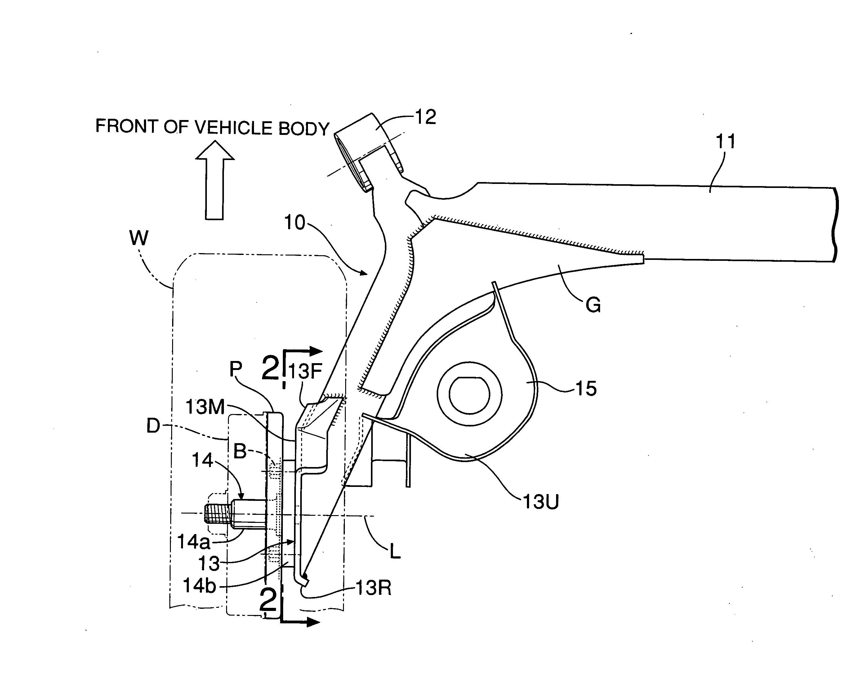
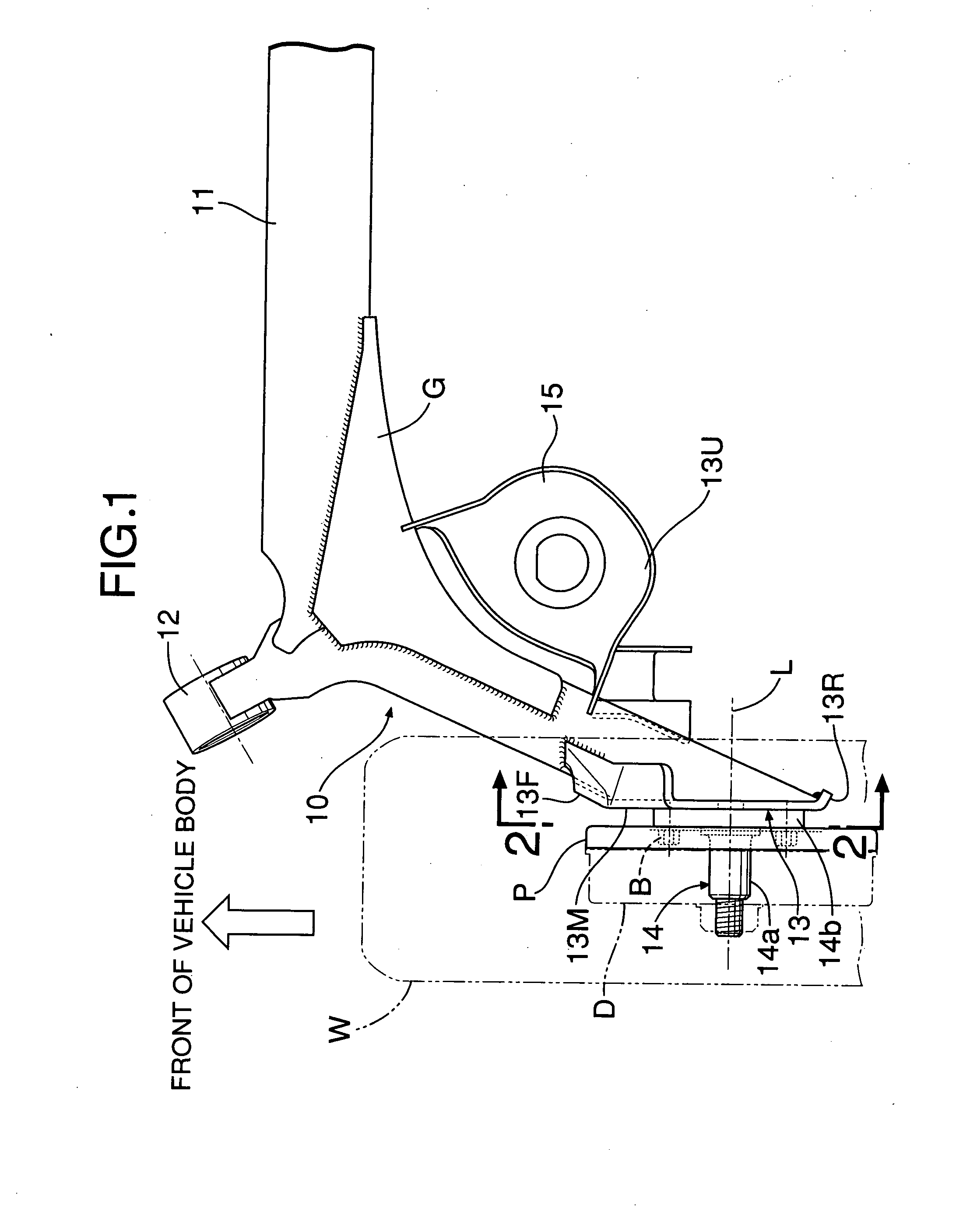
[0075]FIG. 1 to FIG. 5 show a first embodiment of the present invention.

[0076] Firstly, FIG. 1 is a plan view of a left half of a torsion beam suspension for a rear wheel of an automobile; a right half has a symmetrical structure relative to a longitudinally central line of a vehicle body. This torsion beam suspension includes a pair of left and right trailing arms 10 extending substantially linearly in a substantially longitudinal direction of the vehicle body and a torsion beam 11 extending in a substantially lateral direction of the vehicle body and integrally joining the left and right trailing arms 10, and a gusset G is welded between an end part of the torsion beam 11 and a middle part of the trailing arm 10, the gusset G enhancing the strength of the joint therebetween.

[0077] A cylindrical trailing arm support part 12 is welded to the front end of each trailing arm 10, and the front end of each trailing arm 10 is pivotably supported on the vehicle body in a vertically swing...

embodiment 2

[0101] A second embodiment of the present invention is now explained by reference to FIG. 8 to FIG. 12. Since the basic structure of a torsion beam suspension of the second embodiment is the same as that of the first embodiment, each component is denoted by a number obtained by adding 100 to the reference numerals and symbols of the corresponding component of the first embodiment, and explanation of the basic structure is not repeated. It is mainly parts that are different from the first embodiment that are explained below.

[0102] A spindle support plate 113 has a substantially rectangular plate main body 113M, and an open end face 110a at the rear end of a trailing arm 110 is butt-welded w11 to the rear face of the plate main body 113M. The surface of the plate main body 113M (left-hand face in FIG. 10) is a flat mounting seat face for a spindle 114, and the reverse side thereof is provided with four nuts Nfu, Nfd, Nru, and Nrd as four threaded hole portions into which four bolts B...


PUM


Abstract

A torsion beam suspension is provided in which an open end face at the rear end of a trailing arm is butt-welded to a spindle support plate, wherein a front bent flange (13F) is provided integrally with a front end part of a plate main body (13M) of the spindle support plate (13), the front bent flange (13F) extending forward along an outer face of a rear end part of the trailing arm (10) and having its front edge welded (w3) to the outer face of the rear end part, and a rear bent flange (13R) is provided integrally with a rear end part of the plate main body (13M), the rear bent flange (13R) engaging with and being welded (w4) to a rear edge part of the trailing arm (10), a spindle base plate (14b) being superimposed on and secured (w2) to an outer face of the plate main body (13M) and comprising four threaded hole portions (Sfu, Sfd, Sru, Srd) for bolting a brake related plate-shaped component (P) to the spindle base plate (14b), the four threaded hole portions (Sfu, Sfd, Sru, Srd) being at front, rear, upper, and lower positions with the spindle axis interposed therebetween. This enables the spindle support plate to be made thin while suppressing the influence of thermal distortion from welding, thus achieving light weight and a low cost.

Description

TECHNICAL FIELD [0001] The present invention relates to a torsion beam suspension in which opposite ends of a torsion beam extending in a substantially lateral direction of a vehicle body are connected to left and right trailing arms extending in a substantially longitudinal direction of the vehicle body and swinging vertically, and a spindle for axially supporting a wheel is fixed to a spindle support plate welded to the left and right trailing arms. BACKGROUND ART [0002] Conventionally, such a torsion beam suspension is known, as disclosed in, for example, Patent Publication 1 below, and in this arrangement since the trailing arm is in the form of a hollow pipe, a closed cross-section arm structure having good cross-sectional efficiency can be obtained using relatively low cost production equipment. [0003] In this known arrangement, in order to reduce the influence of thermal distortion from welding by spacing the welded joint away from a seating face for mounting the spindle, a l...

Claims


Application Information

Patent Timeline
IPC IPC(8): B60G9/04
CPCB60G7/008B60G21/051B60G2206/8201B60G2206/50B60G2206/20
Inventor INOUE, MITSURUKIKUCHI, FUMIO
Owner F TECH INC
Learn More