
Digital branch calibrator for an RF transmitter

a digital branch and transmitter technology, applied in the field of digital branch calibrators, can solve problems such as unfavorable phasor gain and phase imbalance, and the design of analog circuits is difficult, and the effect of such designs is not good

Inactive Publication Date: 2007-12-20
ZARBANA DIGITAL FUND
View PDF15 Cites 10 Cited by
  • Summary
  • Abstract
  • Description
  • Claims
  • Application Information

AI Technical Summary

Benefits of technology

[0006] The present invention provides a digital (computational) branch calibrator which uses a feedback signal sensed through a passive coupler in the RF transmit signal path following the combining stage of LINC circuitry of a transmitter to compensate for gain and phase imbalances occurring between branch fragment signals leading to the combiner.
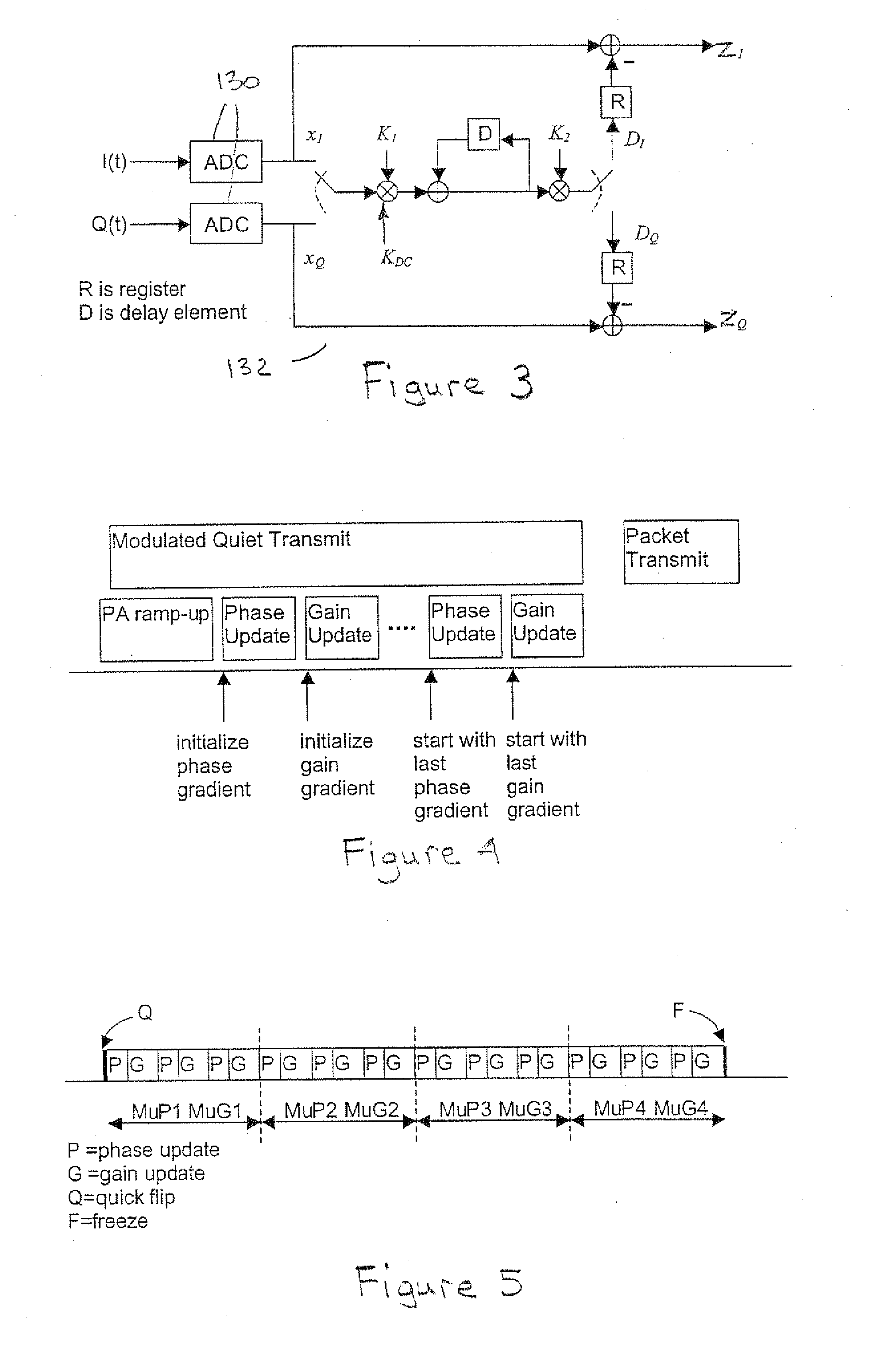
[0008] Also advantageously, the calibrator performs calibration by alternating phase and gain adjustments with programmable and multiple update parameters stages (speeds). This allows a finding of the tougher ‘minima’ in the ‘error surface’ (these being the technical terms used in the field of optimization).
[0010] In addition, the digital processing performed by the calibrator allows the signal level at least one DAC of the DAC pair to be pinned to a specified level, typically that level which is the maximum supported by the DAC, to ensure maximum use of the range of the DAC. This reduces quantization noise and maximum drive (input power level) into at least one of the branch power amplifier's (PA's) to improve the overall efficiency of the power amplifier with combiner (PA / C).

Problems solved by technology

While the Chireix architecture provides certain advantages, the interchip connection between the RF front end and the power amplifier with combiner (PA / C) introduces undesirable phasor gain and phase imbalances (misalignment between the two signals as they proceed independently along that path).
In the past these imbalances have been addressed through the use of analog calibrators within the RF analog circuitry but the design of such analog circuits is very difficult and the effectiveness of such designs has not been good.

Method used


Image

  • Digital branch calibrator for an RF transmitter
  • Digital branch calibrator for an RF transmitter
  • Digital branch calibrator for an RF transmitter

Examples


Embodiment Construction

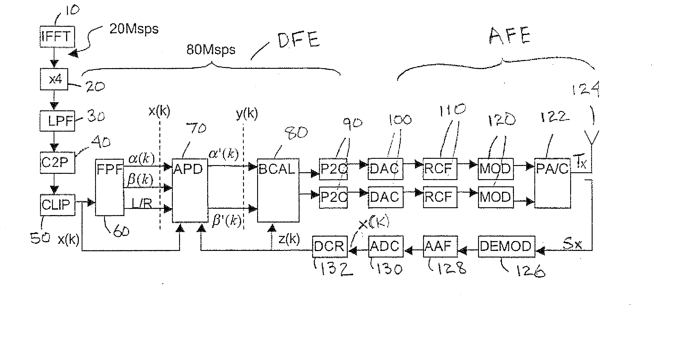
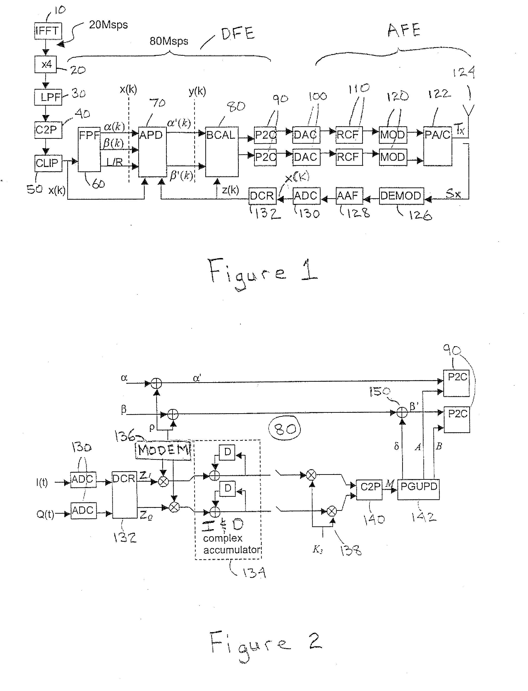
[0027]FIG. 1 is a block diagram of a transmitter circuit of which there is a digital front end (DFE) followed by analog circuitry (AFE) for RF modulation (up-conversion), power amplification and combining before transmission (radiation) from an antenna 124. As shown, in the digital front end an IFFT 10 block performs OFDM modulation on the information signal input thereto at the indicated rate of 20 Mega samples per second (Msps). An up-sampler component 20 increases the sample rate by four times to 80 Msps and the signal sample then passes through a low pass filter component 30. Cartesian-to-polar signal conversion 40 calculates the polar components corresponding to the quadrature (I and Q) signal components and a clipping process 50 clips signal peaks, both of these process being embedded within the phasor fragmenter component 60 (these being shown separately in FIG. 1 for illustrative purposes). The flipping phasor fragmenter (FPF) 60 (which is the subject of pending U.S. patent ...


PUM


Abstract

The present invention provides a digital (computational) branch calibrator which uses a feedback signal sensed from an RF transmit signal path following the combining stage of LINC circuitry of a transmitter to compensate for gain and phase imbalances occurring between branch fragment signals leading to the combiner. The calibrator feeds a quiet (zero) base band signal through the transmit path during the calibration sequence (i.e. a period when data is not transmitted) and adjusts the phase and gain of the phasor fragment signals input thereto by driving the sensed output power to zero. The calibration is performed by alternating phase and gain adjustments with predetermined (programmable) and multiple update parameters stages (speeds). A baseband modulation is preferably used to distinguish false leakage (e.g. due to local oscillator, LO, feed through and DC offset in the base band Tx) from imbalance leakage.

Description

FIELD OF INVENTION [0001] The invention generally relates to devices and modules for radio frequency (i.e. “RF” or “wireless”) transmitters and, in particular, a digital (computational) branch calibrator configured for compensating for fragment signal gain and phase imbalances (misalignment) created in branch signal paths extending between signal fragmentation and combining stages of a transmitter. The invention is specifically applicable but not limited to a branch calibrator for use in a Chireix-type power amplification system. BACKGROUND [0002] The need for efficiency is a particularly important design factor for the highly integrated requirements of transceivers used for wireless local area networks (LANs) and employing non-constant envelope modulation formats such as OFDM (Orthogonal Frequency Division Multiplex) which produce signals having relatively high peak-to-average power ratios. The assignee of this invention and application has developed computational transmitter circu...

Claims


Application Information

Patent Timeline
Patent Type & Authority Applications(United States)
IPC IPC(8): H03K7/06H04L1/00H04L5/12H04L27/26H04L27/36
CPCH04L27/368H04L27/2626
Inventor SAED, ARYAN
Owner ZARBANA DIGITAL FUND
Learn More