Making glazed panels puttied with hot melt adhesive

a technology of hot melt adhesive and glazed panels, which is applied in the direction of ceramic layered products, coatings, transportation and packaging, etc., can solve the problem of unpleasant odor in the area of putty used

a technology of hot melt adhesive and glazed panels, which is applied in the direction of ceramic layered products, coatings, transportation and packaging, etc., can solve the problem of unpleasant odor in the area of putty used

US20070292694A1Inactive Publication Date: 2007-12-20STREUTER TECH

Image

  • Making glazed panels puttied with hot melt adhesive
  • Making glazed panels puttied with hot melt adhesive
  • Making glazed panels puttied with hot melt adhesive

Examples


Embodiment Construction

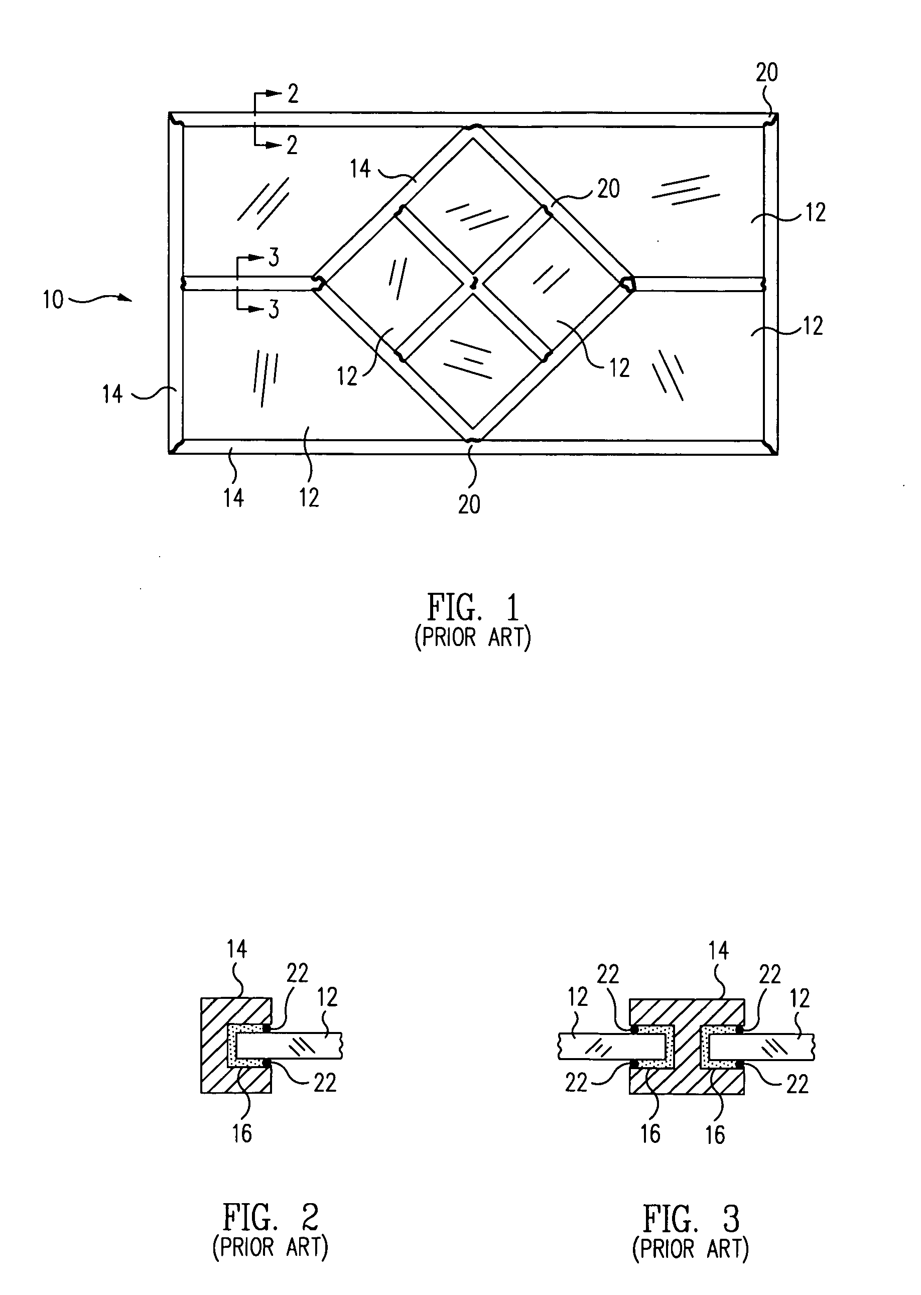
[0020]FIG. 1 is a front elevation view of an exemplary embodiment of a glazed panel 10, such as a stained glass window panel, in accordance with the prior art. As may be seen by reference to the figure, the exemplary glazed panel comprises a plurality of glass pieces, or panes 12, that may be clear, colored, leaded, or painted with translucent, colored designs that may be painted on and / or fired into the glass, and which are arranged in a flat, two-dimensional pattern or matrix and joined together at adjacent opposing edges by means of an elongated rod or bar 14 of a soft metal called a came. The came is typically made of lead or an alloy thereof and contains either one or two U-shaped channels 16 into which the peripheral margins of the glass pieces are inserted. However, the came can also be made of other pliable metal or non-metallic materials, e.g., copper or plastic.

[0021]As illustrated in the cross-sectional view of FIG. 2, a came 14 having only a single elongated channel 16 i...


PUM

PropertyMeasurementUnit
melting pointaaaaaaaaaa
thicknessaaaaaaaaaa

Abstract

A method for making a glazed panel, such as a stained glass window, using a hot melt adhesive instead of a conventional, noisome, slow-drying putty, includes the provision of a glass pane, such as a leaded or stained glass pane, having a peripheral margin, a soft metal came, such as a lead came, having a U-shaped channel configured to receive the peripheral margin of the glass pane, and an elongated strip of a hot melt adhesive disposed in the channel of the came. The glass pane is heated, e.g., with a hot air gun, to a temperature above the melting point of the adhesive and its peripheral margin is then inserted into the channel of the came such that the heated peripheral margin of the glass causes the adhesive to melt and adhere the peripheral margin of the glass pane to the interior surface of the channel of the came.

Description

BACKGROUND[0001]This invention relates to making glazed panels, such as leaded glass or stained glass windows, using a hot melt (HM) adhesive instead of conventional glazing putty.[0002]Glazed panels incorporating leaded and / or stained glass panes have been used as decorative windows in furniture and buildings, such as churches and monasteries, for many centuries, and the process used for their manufacture has remained relatively unchanged during that time. Glazed panels comprise a plurality of glass pieces, or panes, that are clear, colored, leaded, or which incorporate simple or elaborate painted designs that may be fired into the glass, and which are arranged in a flat, two-dimensional pattern and joined together at adjacent opposing edges by means of a “came,” i.e., an elongated rod or bar of a soft metal, typically lead or a lead alloy of variable hardness, containing either one or two U-shaped channels into which the peripheral margins of the glass pieces are received. Came wi...

Claims


Application Information

Patent Timeline
20 Dec 2007
Publication
US20070292694A1
IPC
B05D5/10; B32B18/00; B32B17/06
CPC
C03C27/048; Y10T428/24926; E06B3/68
Inventors
RAUCH, ROBERT A.