
Apparatus and method for easing use of a spectrophotometric based noninvasive analyzer

a non-invasive, spectrophotometric technology, applied in the field of apparatus and methods for easing the use of a spectrophotometric based non-invasive analyzer, can solve the problems of inconvenient use, inconvenient use, and inability to accurately measure glucose, so as to improve detection accuracy, increase detection ease, and increase the accuracy of near-ir based non-invasive glucose determination

Inactive Publication Date: 2007-12-20
GLENN PATENT GROUP
View PDF7 Cites 101 Cited by
  • Summary
  • Abstract
  • Description
  • Claims
  • Application Information

AI Technical Summary

Benefits of technology

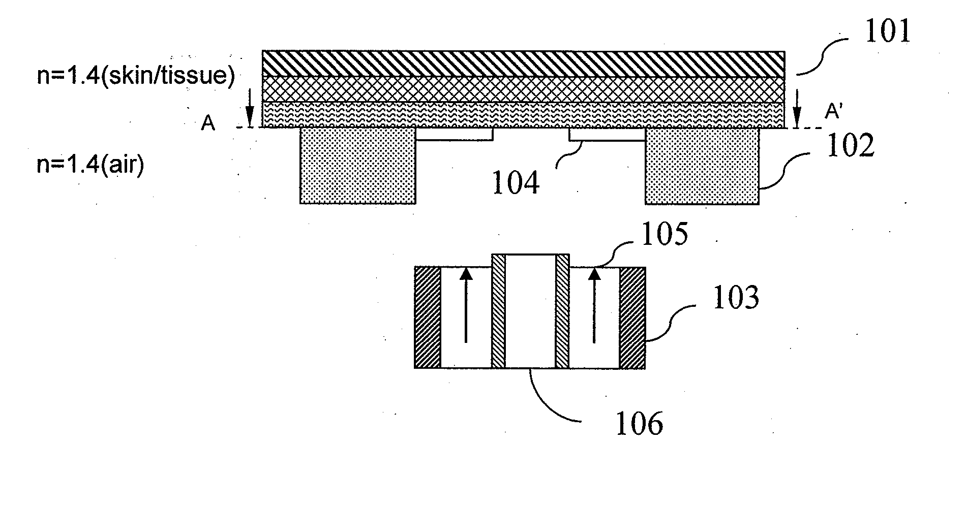
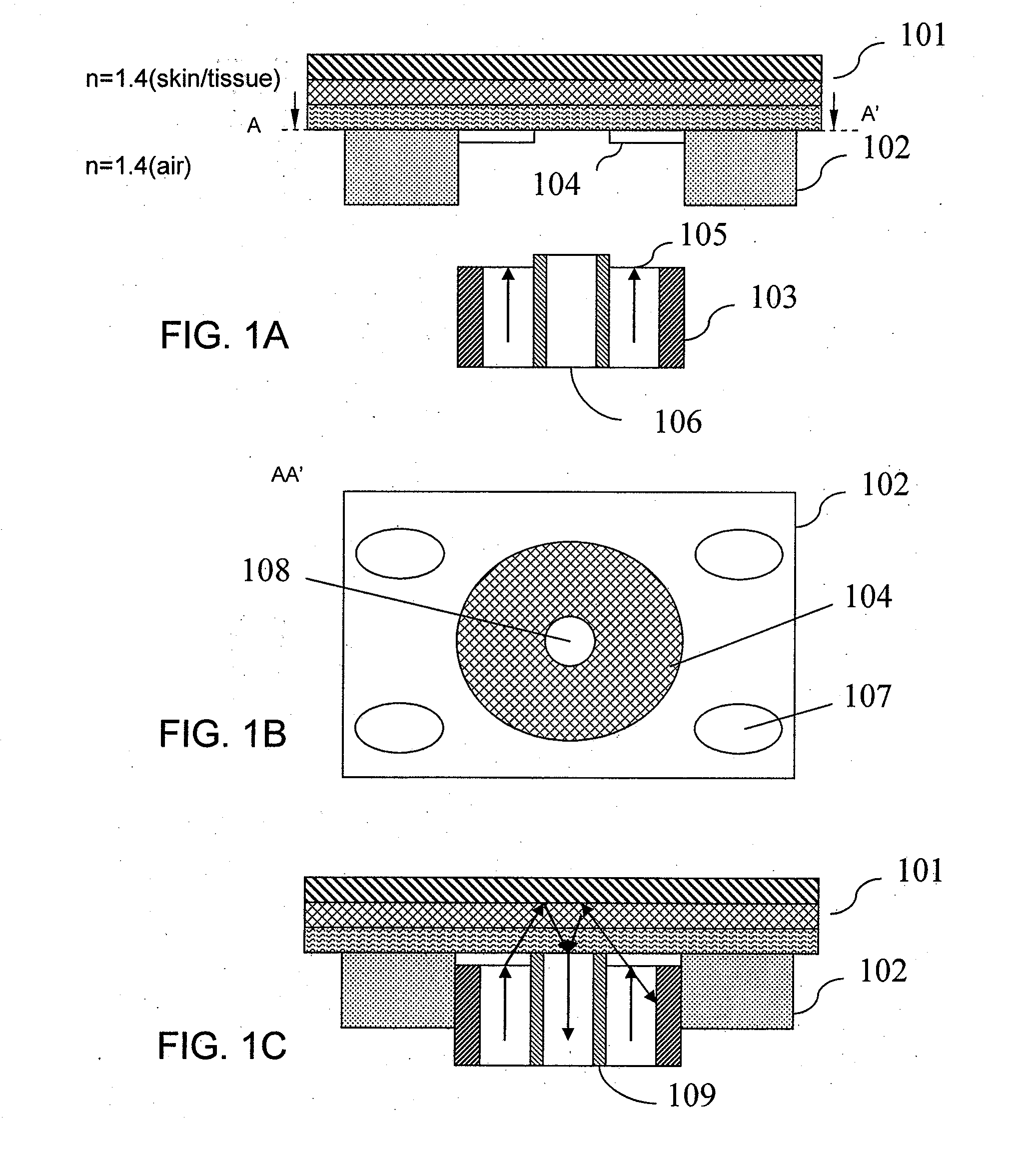
[0047] In another embodiment, there is a hole in the center of the hydration inducing plug, so that when the optical probe is coupled with the guide, the collection optics of the optical probe is fittingly coupled into the hole and has direct contact with the sampling site, while the incident optics of the optical probe maintains direct contact with the surrounding area of the hydration inducing plug. To increase detection, the hydration inducing plug may be shaped as an optical convexity. In that case, the incident photons travel in the air for a short distance before they reach the inner surface of the plug.
[0048] Yet in another embodiment, the guide contains one or more reservoirs for containment of an optical coupling fluid that may be near-IR inactive. A guide incorporating at least one of these couplers allows for increased ease of use and increased in precision and accuracy of near-IR based noninvasive glucose determinations. The modified guide allows for automated, semi-automated, or simplified sampling associated with a near-IR based noninvasive glucose analyzer or for separate optical analyses that use a guide.
[0049] The hydration inducing plug, also called hydration inducer coupler, replaces an older plug that has to be manually removed between samples. The removal and replacement after sampling of the plug results in several issues such as: (1) time involved; (2) manually dexterity; (3) introduction of pressure transients; (4) introduction of temperature transients; (5) possibility of loss of removable item; and (6) possibility of introducing contaminants to the sampling site. The hydration inducing plug according to the invention mitigates all of these issues.
[0050] The guide coupling fluid reservoir simplifies application of a coupling fluid. To date, application of coupling fluid to a measurement site has been achieved by manually placing an externally stored fluid onto the sampling site. There are many issues related to this including: (1) time involved; (2) manual dexterity requirements; (3) external storage space required; (4) portability concerns such as carrying the coupling fluid for use with a portable analyzer; (5) introduction of pressure transients, such as bumping the sampling site when applying the coupling fluid; and (6) introduction of temperature transients, such as applying a cold coupling fluid to the sampling site. The coupling fluid reservoir scheme according to the invention allows for automated, semi-automated, or simplified coupling fluid application that mitigates all of these issues.

Problems solved by technology

Diabetes is a chronic disease that results in improper production and utilization of insulin, a hormone that facilitates glucose uptake into cells.
Diabetes is a leading cause of death and disability worldwide.
However, current monitoring techniques discourage regular use due to the inconvenient and painful nature of drawing blood through the skin prior to analysis.
A disadvantage of this system is that it does not efficiently collect diffusely reflected light and the alignment is problematic.
Further, no suggestion is made for a fluoropolymer hydration inducer or for a coupling fluid reservoir within the guide.
In addition, to date no FDA device has been approved for the utilization by an individual or a medical professional for noninvasive glucose concentration determination.
The measurement is complicated by every manual step required in the spectral acquisition process utilized in a given glucose determination.
Specifically, preparation of the sampling site in terms of temperature, historesis of applied pressure, hydration, and optical scattering parameters involving actions from the user that may be any of technically challenging, time consuming, and error inducing.

Method used


Image

  • Apparatus and method for easing use of a spectrophotometric based noninvasive analyzer
  • Apparatus and method for easing use of a spectrophotometric based noninvasive analyzer
  • Apparatus and method for easing use of a spectrophotometric based noninvasive analyzer

Examples


Embodiment Construction

[0061]FIG. 1A is a schematic diagram showing the front, cross-sectional view of a piece of sampling skin, a placement guide in contact with the sampling skin, and an optical probe which has not yet been coupled with the guide according to one embodiment of the invention. In FIG. 1A, skin 101 is schematically represented in layers. These layers include the stratum corneum, epidermis, dermis, and adipose tissue, as well as underlying structures, such as muscle. Each of these layers includes many sub-layers and structures. The guide includes a mount 102, also called a guide lock, that is semi-permanently attached to a skin surface. The mount 102 may be in any shape, such as substantially rectangular, circular, oval, and polygonal. The guide includes an aperture which is defined by the mount 102. The aperture may be in any shape, such as substantially rectangular, circular, oval, triangular, hexagonal, and polygonal. The guide may be attached for one or more subsequent glucose determina...


PUM


Abstract

A noninvasive glucose concentration analyzer having an optical probe with incident and collection optics and a channel for coupling fluid delivery is disclosed. Fluid is delivered through the channel to a skin tissue site that is subsequently optically sampled using the analyzer.

Description

CROSS REFERENCE TO RELATED APPLICATIONS [0001] This application is a continuation of U.S. patent application Ser. No. 10 / 824,459, filed Apr. 13, 2004, which claims benefits to the U.S. provisional patent application Ser. No. 60 / 463,616 filed on 16 Apr. 2003 the contents of each of which are incorporated herein in their entirety by this reference thereto.BACKGROUND OF THE INVENTION [0002] 1. Field of the Invention [0003] The invention relates generally to the technology of noninvasive analyte determination in the human body. More particularly, the invention relates to the use of a placement guide in conjunction with a diffuse reflectance based near-IR glucose analyzer. The placement guide couples to a glucose analyzer and has at least one of a hydration inducer and a reservoir for a coupling agent used for automatic or manual delivery of the coupling agent to the sampling site. [0004] 2. Description of Related Art [0005] Spectroscopy based noninvasive analyzers deliver external energ...

Claims


Application Information

Patent Timeline
IPC IPC(8): A61N5/06A61B5/00G01N21/35G01N21/47
CPCA61B5/14532A61B5/1455G01N21/474G01N21/359A61B5/6841
Inventor MONFRE, STEPHEN L.ACOSTA, GEORGE M.BLANK, THOMAS B.HAZEN, KEVIN H.
Owner GLENN PATENT GROUP
Learn More