Molded glass substrate for magnetic disk and method for manufacturing the same

a technology of magnetic disks and molded glass, which is applied in the direction of manufacturing tools, instruments, transportation and packaging, etc., can solve the problems of limiting the effort to reduce costs, requiring a lot of time for heating and cooling, and a large amount of industrial waste, so as to reduce industrial waste, eliminate the need for chamfering, and suppress the generation of dust

Inactive Publication Date: 2007-12-27
PANASONIC CORP
View PDF6 Cites 12 Cited by
  • Summary
  • Abstract
  • Description
  • Claims
  • Application Information

AI Technical Summary

Benefits of technology

[0011] The present invention can provide embodiments that are desirable for environmental protection by reducing industrial waste as much as possible with a combination of a molding process and an existing machining process. Also, the present invention allows the outer circumference to be formed as a molding-free face, so that the su...

Problems solved by technology

However, there is a limit to the effort to reduce the cost because the conventional machining method is followed.
The conventional machining method causes relatively a large amount of industrial waste during processing, such as glass powder, abrasive, and solvent, and treatment of the waste is not environmentally preferable.
However, it requires a lot of time for heating and cooling, and the molding process is divided so as to solve that problem.
Though this method can shorten preheating time remarkably, it has drawbacks in precise transcription and problems in energy measures, such as the need for annealing.
The reason for this is as follows: high internal temperatur...

Method used


Image

  • Molded glass substrate for magnetic disk and method for manufacturing the same
  • Molded glass substrate for magnetic disk and method for manufacturing the same
  • Molded glass substrate for magnetic disk and method for manufacturing the same

Examples


embodiment 1

[0042] Hereinafter, a molded glass substrate for a magnetic disk of Embodiment 1 of the present invention will be described with reference to FIG. 1, and press-molding and processing methods for producing the molded glass substrate will be described with reference to FIGS. 2, 3, 4, and 5A to 5C.

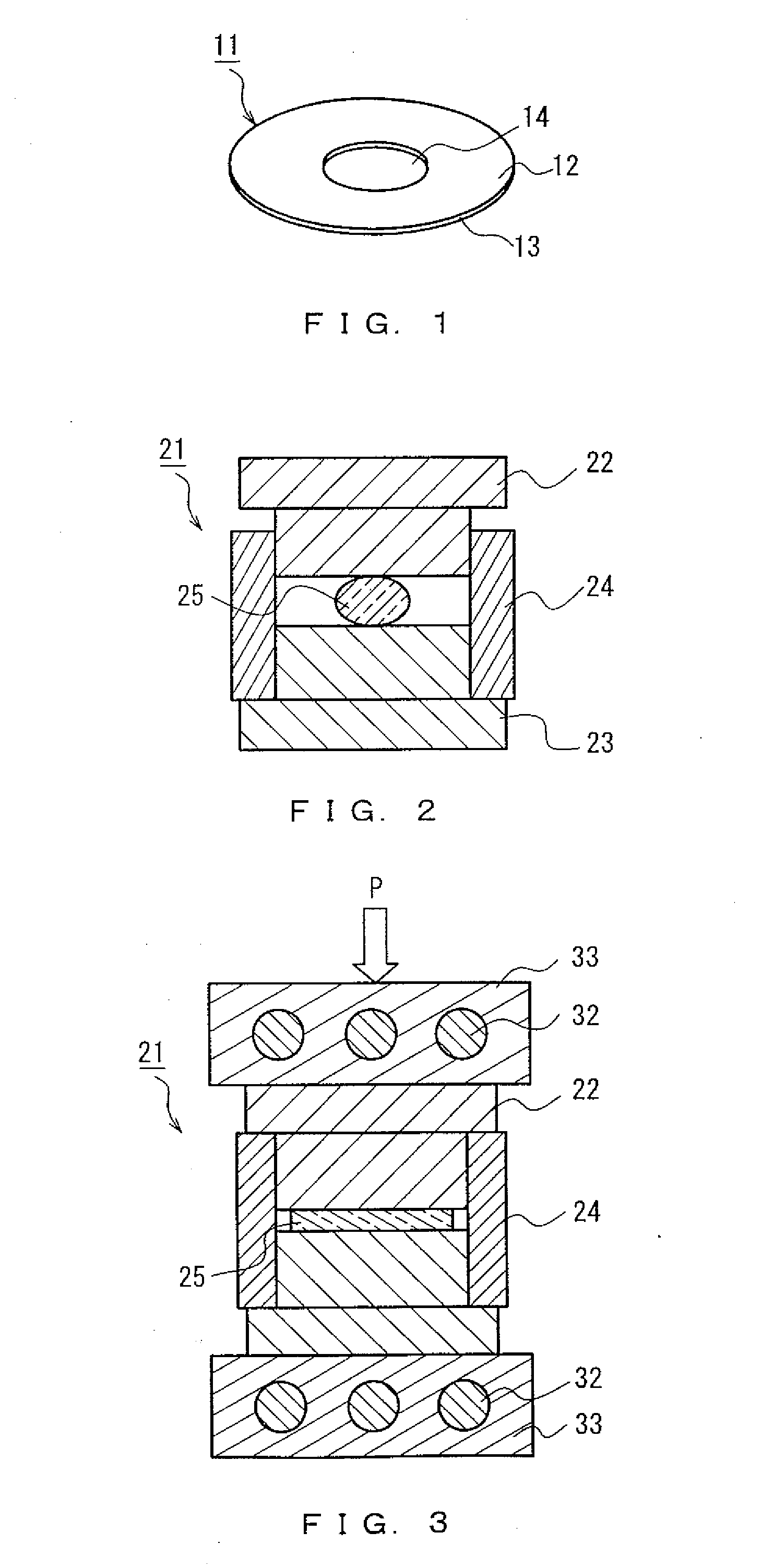
[0043]FIG. 1 shows a molded glass substrate 11 for a magnetic disk, including principal surfaces 12, a molding-free face 13, and an inner surface 14: the principal surfaces 12 are formed on both sides of the substrate by precise press-molding; the molding-free face 13 is the outer surface joined to the principal surfaces; and the inner surface 14 is formed by precise machining.

[0044] The precisely processed surfaces of a molding die are transcribed faithfully onto the principal surfaces 12. The molding-free face 13 is not controlled by the processed surfaces of dies during molding. In general, the inner and outer circumferences of a magnetic disk glass substrate are ground and chamfered, an...

embodiment 2

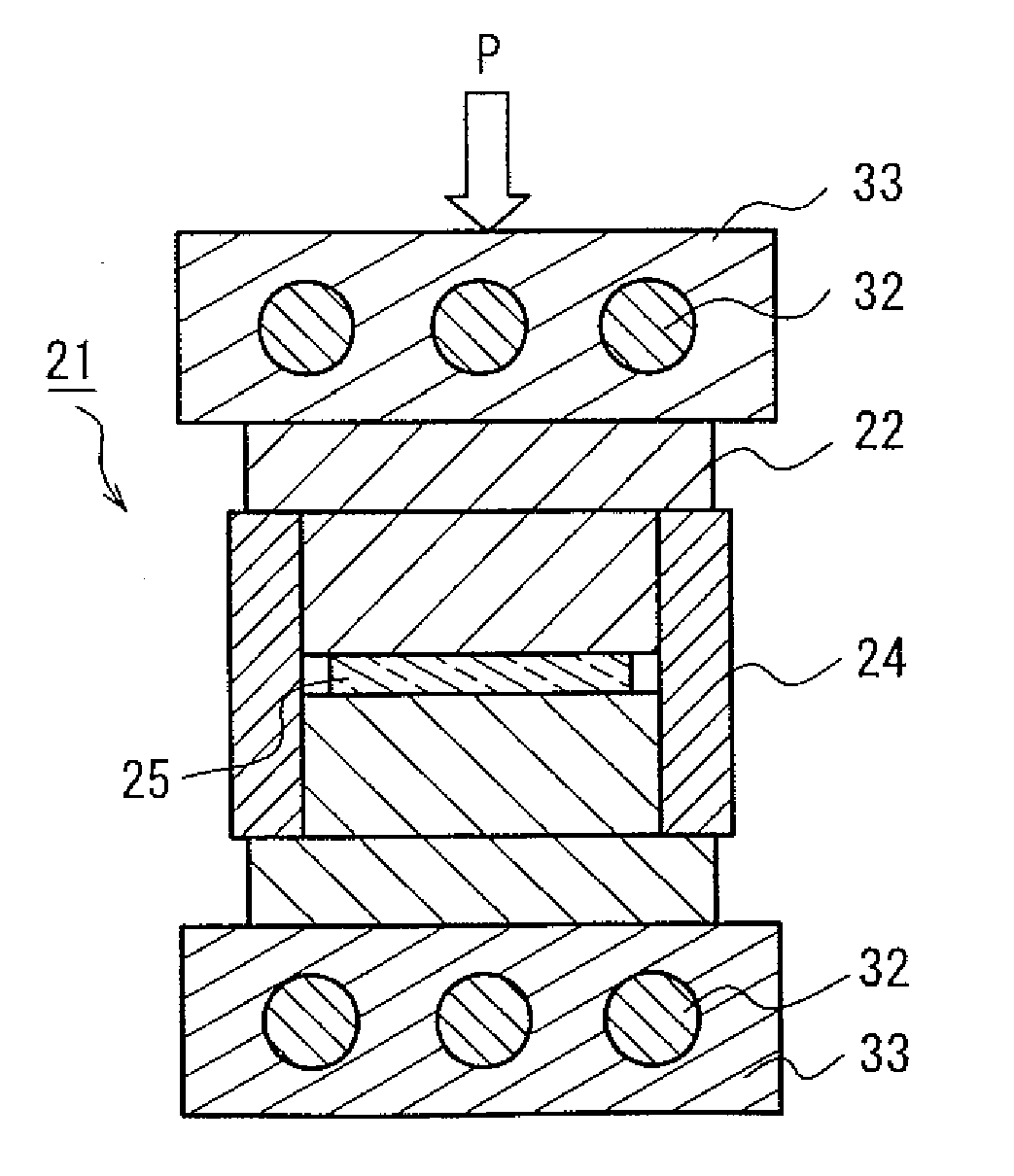
[0047] The schematic configurations of a molding die and a molding apparatus will be described with reference to FIGS. 2, 3, and 4. L In FIG. 2, a molding block 21 includes an upper die 22, a lower die 23, and a barrel die 24. Each of the upper and lower dies 22, 23 has a molding face that is processed precisely to have a desired mirror-finished surface. The barrel die 24 guides the upper and lower dies in a slidable fashion. A glass material 25 is placed in a space between the upper, lower, and barrel dies.

[0048]FIG. 3 shows the schematic configuration of a press-molding apparatus 31 that heats the entire molding block 21. The press-molding apparatus 31 includes upper and lower heating plates 33 arranged above and under the molding block 21, each heating plate containing a heater 32, and a mechanism for applying pressure via the upper heating plate 33, which is not shown and indicated by the arrow P in FIG. 3. Except for the pressurizing mechanism, the upper and lower heating plat...

embodiment 3

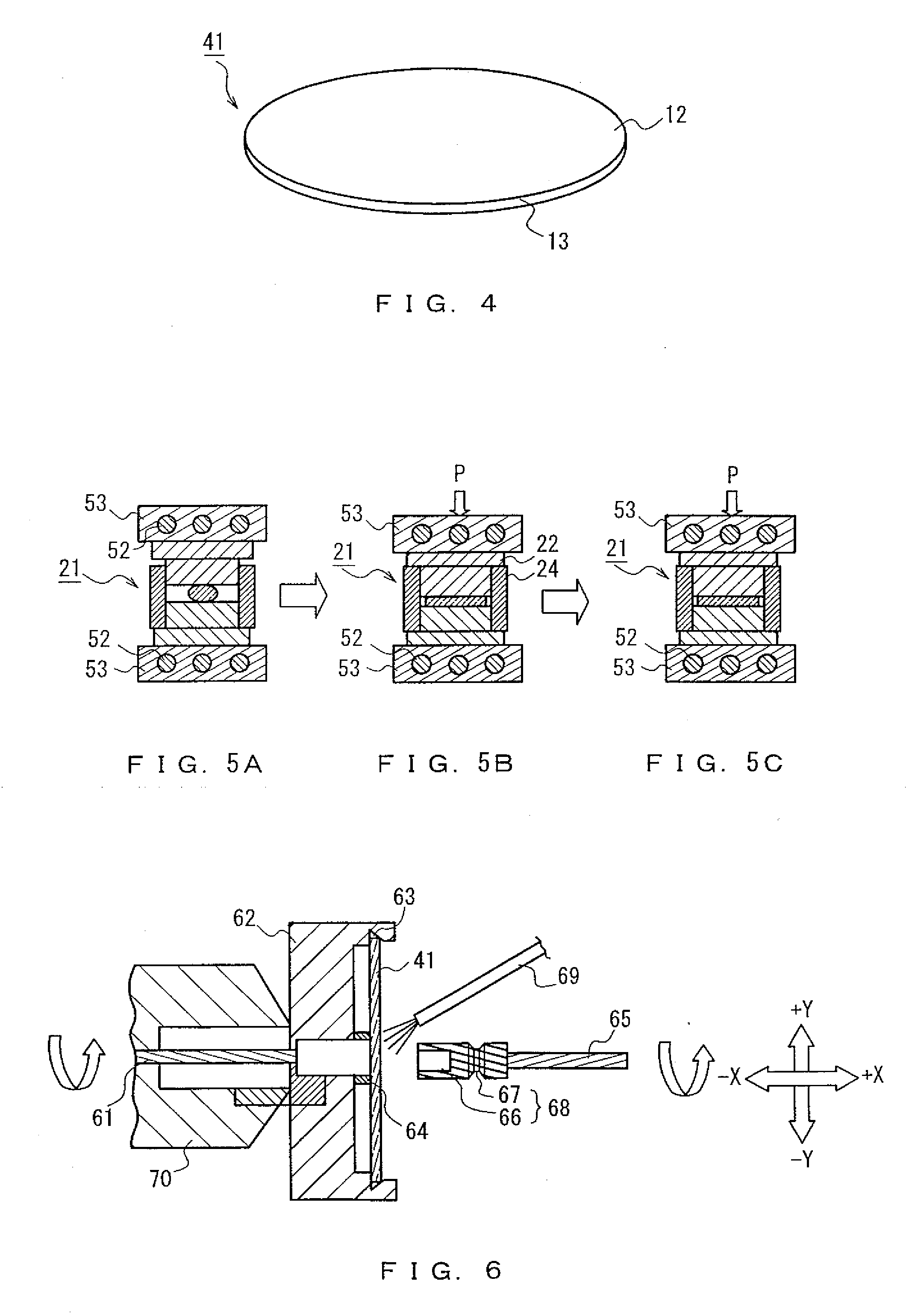
[0053] Next, to obtain the molded glass substrate for a magnetic disk of Embodiment 1 of the present invention shown in FIG. 1, the concept of a press-molding method different from the above method will be described with reference to FIG. 5 so that the molded glass substrate 41 can be produced.

[0054]FIG. 5A shows a preheating step: a molding block 21 similar to that in FIG. 2 is preheated throughout with upper and lower heating plates 53, each of which is heated at a steady temperature and controlled by a heater 52, while the molding block 21 is kept waiting for a certain time. Then, the molding block 21 is conveyed to a transforming step shown in FIG. 5B. In the transforming step, a pressurizing mechanism (not shown) applies pressure P so as to transform a glass material 25, and the transformation is completed when an upper die 22 comes into contact with a barrel die 24 in the same manner as shown in FIG. 3. In FIG. 5C, a cooling step is performed with the application of pressure ...


PUM

PropertyMeasurementUnit
Nanoscale particle sizeaaaaaaaaaa
Temperatureaaaaaaaaaa
Pressureaaaaaaaaaa

Abstract

A method for manufacturing a glass substrate for a magnetic disk involving press-molding a heated glass material in an inside space of a molding die comprising a pair of dies, each having a predetermined processing plane, and a barrel die for slidably guiding the dies while forming an outer circumference of the glass material joined to both principal surfaces corresponding to the dies as a molding-free face, cooling the press-molded glass substrate and forming a predetermined through-hole in a central portion of the glass substrate.

Description

BACKGROUND OF THE INVENTION [0001] 1. Field of the Invention [0002] The present invention relates to a molded glass substrate for a magnetic disk used in computer memory devices or the like and a method for manufacturing the same. [0003] 2. Description of the Related Art [0004] In magnetic disks, the conflicting technological problems of high capacity and low cost have been addressed recently. To provide desired flatness and smoothness, a conventional disk, which uses aluminum as a base material, requires many complicated manufacturing processes by machining based on the methods of grinding and polishing. On the other hand, glass substrates with excellent rigidity and hardness are smoothed easily, so that they can satisfy high capacity and high reliability at the same time. However, there is a limit to the effort to reduce the cost because the conventional machining method is followed. The conventional machining method causes relatively a large amount of industrial waste during proc...

Claims


Application Information

Patent Timeline
IPC IPC(8): C03B11/05B28D1/04B32B3/02C03B11/08G11B5/73G11B5/84
CPCB28D1/041B32B3/02C03B11/088Y10T428/24347G11B5/7315G11B5/8404Y10T428/218C03B2215/44G11B5/73921
Inventor NAKAMURA, SHOJIKONDOU, TAKAHISAKATAOKA, HIDENAOSHIMIZU, YOSHIYUKI
Owner PANASONIC CORP
Why Eureka
Try Eureka