Ground shield with reentrant feature

Active Publication Date: 2007-12-27
APPLIED MATERIALS INC
View PDF8 Cites 245 Cited by
  • Summary
  • Abstract
  • Description
  • Claims
  • Application Information

AI Technical Summary

Problems solved by technology

If enough material from the target is deposited on the ground shield during PVD processing, the deposited material may bridge the gap a

Method used


Image

  • Ground shield with reentrant feature
  • Ground shield with reentrant feature
  • Ground shield with reentrant feature

Examples


Embodiment Construction

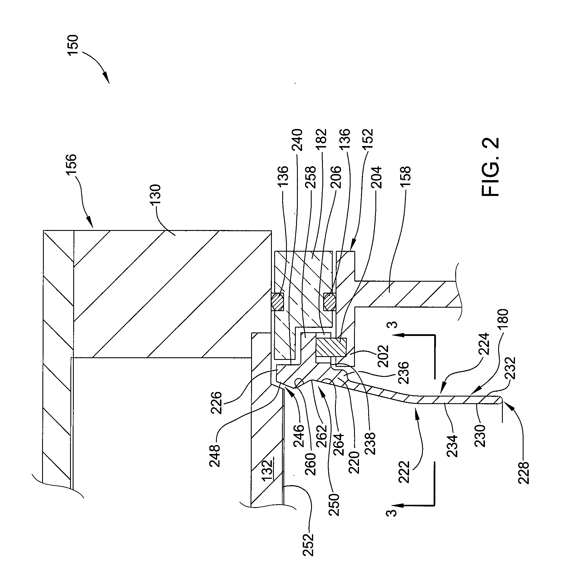
[0015]The invention generally provides a ground shield for use in a physical vapor deposition (PVD) chamber. The ground shield advantageously prevents arching between the shield and target, which promotes greater process uniformity and repeatability along with longer chamber component service life.

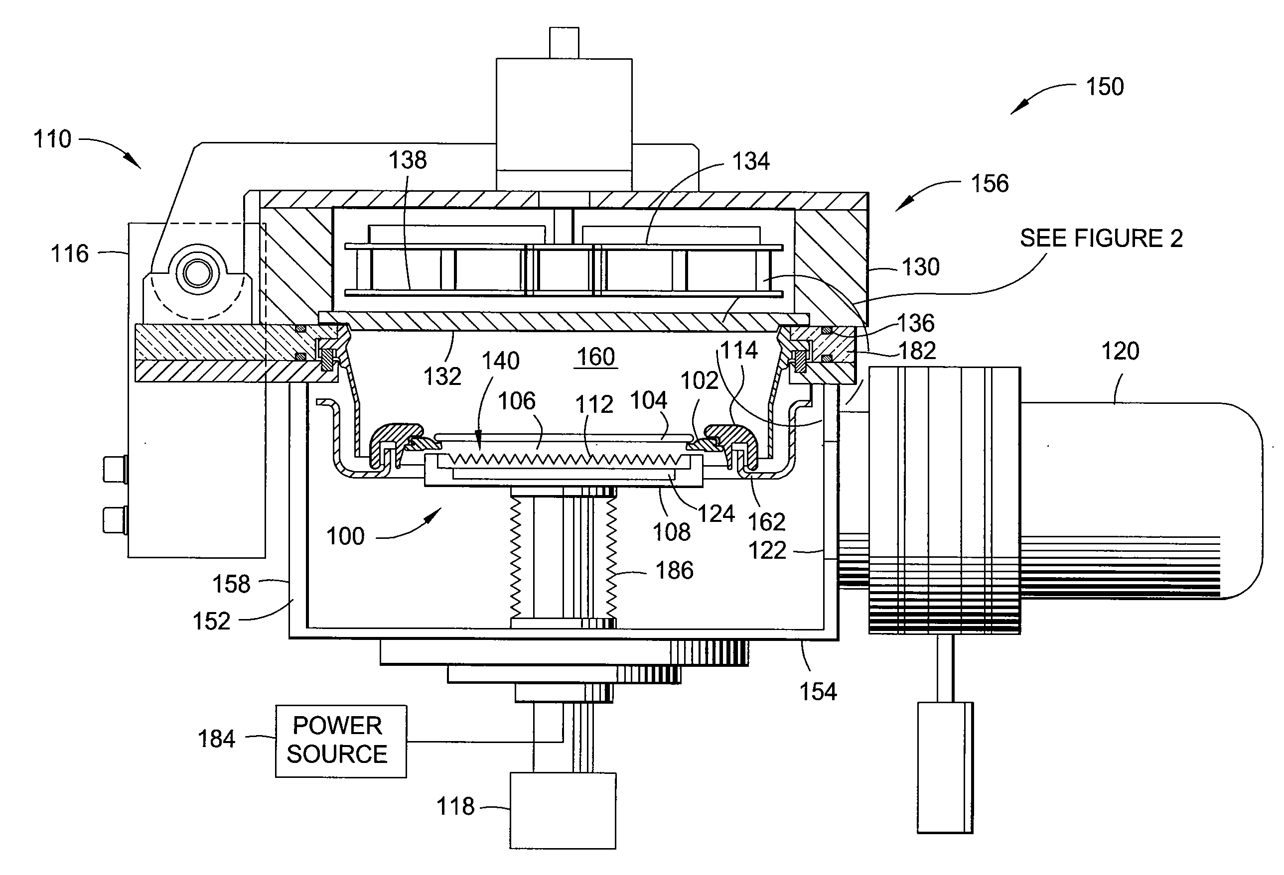
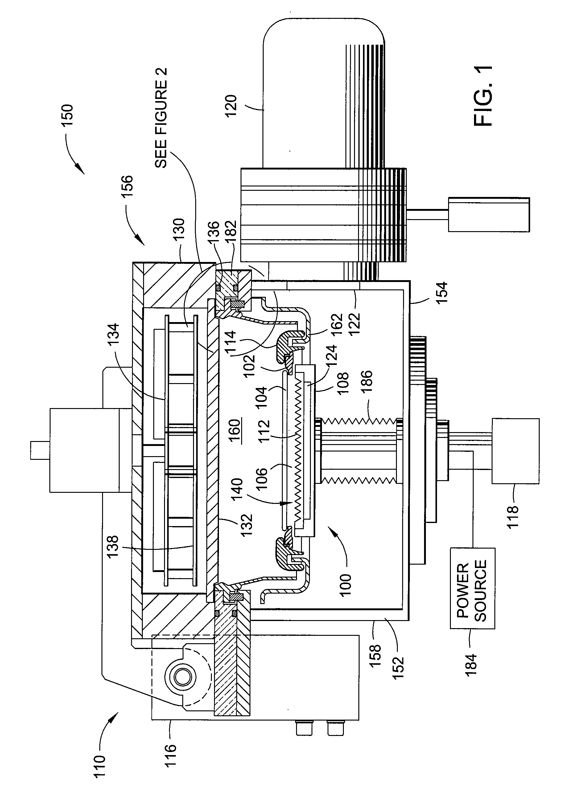
[0016]FIG. 1 depicts an exemplary semiconductor processing chamber 150 having one embodiment of a ground shield 180. One example of a processing chamber that may be adapted to benefit from the invention is an IMP VECTRA™ PVD processing chamber, available from Applied Materials, Inc., of Santa Clara, Calif. It is contemplated that other processing chambers, including those from other manufacturers, may be adapted to benefit from the invention.

[0017]The exemplary processing chamber 150 includes a chamber body 152 having a bottom 154, lid assembly 156 and sidewalls 158 that define an evacuable interior volume 160. The chamber body 150 is typically fabricated from welded plates of stainless st...


PUM

PropertyMeasurementUnit
Diameteraaaaaaaaaa
Electrical conductoraaaaaaaaaa

Abstract

The invention generally provides a ground shield for use in a physical vapor deposition (PVD) chamber. In one embodiment, a ground shield includes a generally cylindrical body comprising an outer wall, an inner upper wall, an inner lower wall having a diameter less than a diameter of the inner upper wall and a reentrant feature coupling the upper and inner lower walls. The reentrant feature advantageously prevents arching between the shield and target, which promotes greater process uniformity and repeatability along with longer chamber component service life.

Description

BACKGROUND OF THE INVENTION[0001]1. Field of the Invention[0002]Embodiments of the invention generally relate to a ground shield for semiconductor processing chamber.[0003]2. Description of the Related Art[0004]Physical vapor deposition (PVD), or sputtering, is one of the most commonly used processes in the fabrication of electronic devices. PVD is a plasma process performed in a vacuum chamber where a negatively biased target is exposed to a plasma of an inert gas having relatively heavy atoms (e.g., argon (Ar)) or a gas mixture comprising such inert gas. Bombardment of the target by ions of the inert gas results in ejection of atoms of the target material. The ejected atoms accumulate as a deposited film on a substrate placed on a substrate pedestal disposed within the chamber.[0005]A ground shield may be disposed in the chamber to help define a processing region in a desired region within the chamber with respect to the substrate. The ground shield helps confine the plasma within...

Claims


Application Information

Patent Timeline
IPC IPC(8): C23C14/00
CPCH01J37/32623H01J2237/026H01J2237/0206H01J37/3405
Inventor TILLER, JENNIFER W.SUBRAMANI, ANANTHACOX, MICHAEL S.MILLER, KEITH A.
Owner APPLIED MATERIALS INC
Why Eureka
Try Eureka