Eureka AIR delivers breakthrough ideas for toughest innovation challenges, trusted by R&D personnel around the world.

Metal inverted F antenna

Inactive Publication Date: 2007-12-27
ARCADYAN
View PDF5 Cites 20 Cited by
  • Summary
  • Abstract
  • Description
  • Claims
  • Application Information

AI Technical Summary

Benefits of technology

[0009] Another object of the present invention is to provide an F-shape antenna to increase the bandwidth.
[0011] Yet another object of the present invention is to provide an antenna structure comprising a radiator having a curved shape portion and a rectangular portion connected to the ground plane such as to improve the performance of the antenna.

Problems solved by technology

The helical antennas or linear monopole antennas have a merit of omni-directional radiation characteristic, since they are of external type projecting outside the device, therefore, they are likely to be damaged by an external force.
Since the miniaturization method used in the conventional antenna is based on a two-dimensional structure, there is a limit to the miniaturization.
However, wireless communication is characterized by limited available frequency spectrum, low transmission powers and limited device processing capability.
Furthermore, narrow bandwidth characteristic of conventional PIFA is one of the limitations for its commercial application for wireless mobile at present.

Method used


Image

  • Metal inverted F antenna
  • Metal inverted F antenna
  • Metal inverted F antenna

Examples


Embodiment Construction

[0022] The preferred embodiments of the present invention will be described in detail with reference to the annexed drawings. In the drawings, the same or similar elements are denoted by the same reference numbers even though they are depicted in different drawings. In the following description, a detailed description of known functions and configurations incorporated herein will be omitted when it may make the subject matter of the present invention rather unclear.

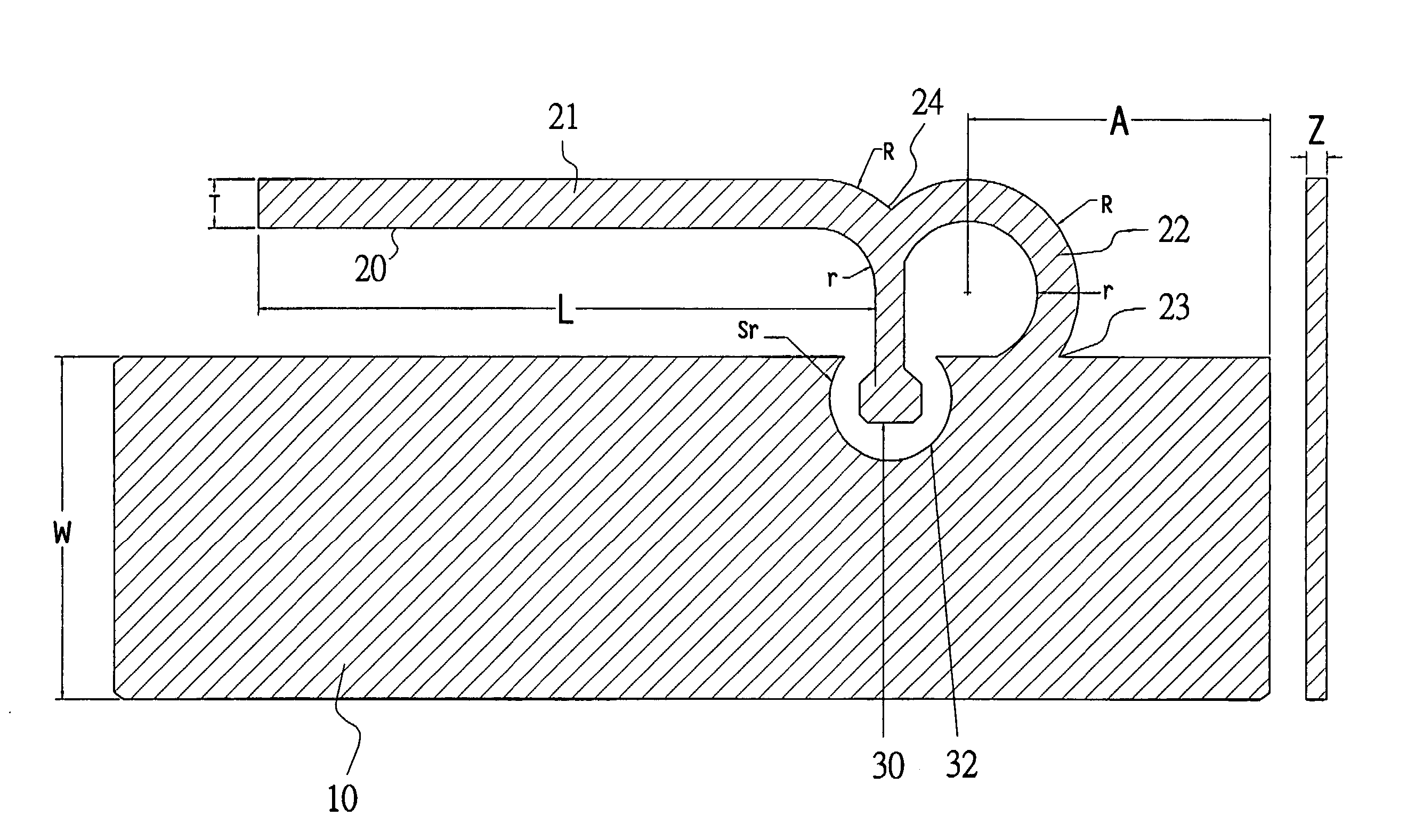
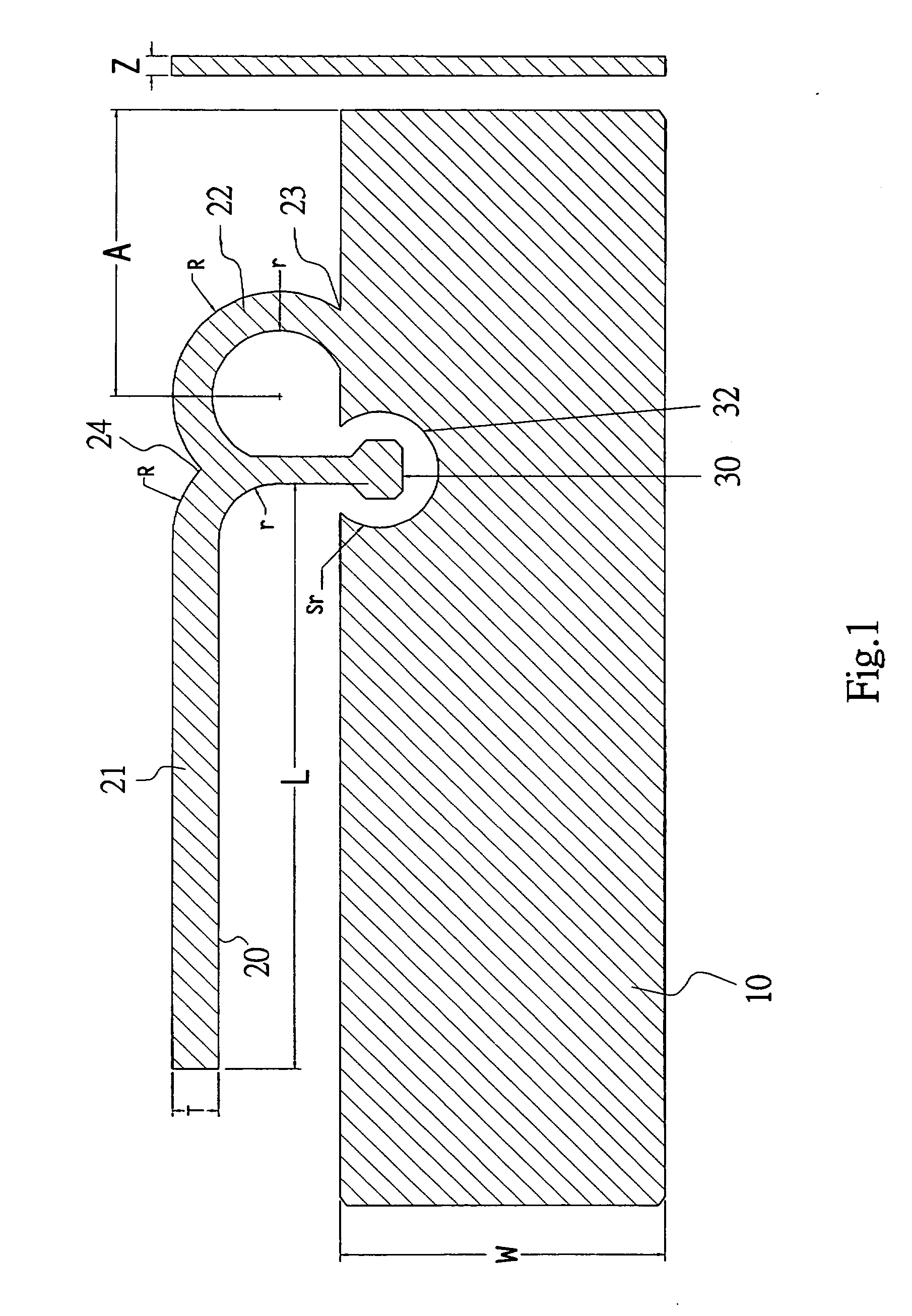
[0023]FIG. 1 is a horizontal schematic diagram of the planar metal inverted F antenna of the present invention. As shown in FIG. 1, a radiation element of the antenna is combined to a ground metal plane 10. The basic properties that are used to describe the performance of an antenna include impedance, voltage standing wave ratio (VSWR) or standing wave ratio (SWR), amplitude radiation patterns, directivity, gain, polarization and bandwidth. In order to achieve maximum power transfer between a wire or coaxial transmission...


PUM


Abstract

The present invention discloses an antenna structure comprising a ground plane; a radiator having a curved shape portion and a rectangular portion connected to the ground plane via a first end of the curved shape portion and grounded by a ground point of the ground plane, the rectangular portion being connected to a second end of the curved shape portion; and a feed point projected into a groove within the ground plane and connected to the second end of the curved shape portion of the radiator; and wherein the ground plane is extended over the rectangular portion of the radiator.

Description

FIELD OF THE INVENTION [0001] The present invention relates generally to antenna structures, and more particularly to a metal inverted F antenna (IFA) with a feed point projected into a curved groove within the ground plane. BACKGROUND OF THE INVENTION [0002] As telecommunication technologies advance from wired to wireless communication driven by efficiency and convenience for the general public in the past decade, wireless communication devices and their implementation have become ubiquitous. Antennas have been a key building block in the construction of every wireless communication system. In many instances, the antenna is not considered critical in the initial system design. However, the antenna is the single device that allows RF energy to transmit between wired transmission lines and free space. Consequently, antennas and propagation are the key factors influencing the robustness and quality of the wireless communication channel. [0003] Typically, conventional helical antennas ...

Claims


Application Information

Patent Timeline
IPC IPC(8): H01Q1/24
CPCH01Q1/243H01Q9/42H01Q9/0421H01Q1/38
Inventor LEE, CHANG-JUNG
Owner ARCADYAN
Why Eureka
Eureka Blog
Learn More