Ink jet recording method and ink jet recording device

a recording method and ink jet technology, applied in the field of ink jet recording method and ink jet recording device, can solve the problems of uneven line width, different images formed, and practicable use, and achieve the effects of preventing the spread of ink dots, improving image sharpness, and increasing the density of surfactan

Inactive Publication Date: 2007-12-27
FUJIFILM CORP
View PDF7 Cites 48 Cited by
  • Summary
  • Abstract
  • Description
  • Claims
  • Application Information

AI Technical Summary

Benefits of technology

[0085] Regarding the physical properties of the ink (liquid droplet) to be ejected onto a recording medium in an ink jet recording method, the viscosity at 25° C. thereof is preferably in the range of from 5 to 100 mPa·s, and more preferably in the range of from 10 to 80 mPa·s, although the value may vary dependent on the type of the devices. The viscosity at 25° C. of the undercoating liquid before being subjected to half-curing is preferably in the range of from 100 to 5000 mPa·s, and more preferably in the range of from 200 to 3000 mPa·s.
[0086] In the invention, the undercoating liquid preferably contains a surfactant from the viewpoint of forming the dots with the desired size onto a recording medium, and preferably satisfies all of the conditions (A), (B), and (C) described below:
[0087] In the above relations, γs is the value of the surface tension of the undercoating liquid; γs (0) is the value of the surface tension of the liquid having a composition of the undercoating liquid from which all surfactants are excluded; γs (saturated) is the value of the surface tension of the liquid, wherein the liquid is obtained by adding one of the surfactants contained in the undercoating liquid to the above “liquid excluding all of the surfactants”, the value being measured when the surface tension reaches a point of saturation as the density of the surfactant is increased; and γs (saturated)max is the maximum value among the values of γs (saturated) respectively measured for all kinds of the surfactants which are contained in the undercoating liquid that satisfy the above condition (B).
[0088] In the invention, the surface tension γs of the undercoating liquid is preferably smaller than the surface tension γk of at least one of the inks in order to form ink dots of desired size onto the recording medium as described above.
[0089] Further, from the viewpoint of preventing the spreading of the ink dots during the period from the landing of the ink droplets up to the exposure more effectively, the values of γs and γk preferably satisfy the relation of γs<γk−3 (mN / m), and more preferably satisfy the relation of γs<γk−5 (mN / m).
[0090] In the case of printing a full-color image, from the viewpoint of improving sharpness of the image, the surface tension of the undercoating liquid γs is preferably at least smaller than the surface tension of the ink containing a coloring agent with high visibility, and more preferably smaller than the surface tensions of all of the inks. The coloring agent with high visibility is, for example, a coloring agent that exhibits the color of magenta, black, or cyan.

Problems solved by technology

However, there have been problems in practical use, particularly in the case of recording on the above described non-absorbing recording medium, e.g., bleeding of an image easily occurs, or mixing of adjacent ink droplets occurs on the recording medium to inhibit formation of a sharp image, when it takes time for the liquid droplets to dry or penetrate into the recording medium after being ejected.
When the liquid droplets mix with each other, ejected adjacent liquid droplets coalesce with each other to shift from the positions at which they have landed, thereby causing unevenness in line width in a case of forming fine lines or unevenness in color in a case of forming a colored area, or the like.
Further, since the degree of occurrence of unevenness in line width or color unevenness in a colored area varies depending on ink absorption and wettability of the surface of the recording medium, there has also been a problem that different images are formed among various types of recording media, even though the same ink is used under the same ejection conditions.
However, in the method described in JP-A No. 2004-42548, although blurring can be suppressed, there still remains the problem of variation in images among various types of recording media, and thus the problem of unevenness in line width, color or the like due to mixing of ink droplets are not sufficiently solved.
This problem of unevenness in line width, color or the like due to mixing of ink droplets are also not sufficiently solved by any of the methods described in JP-A No. 2003-145745, JP-A No. 2004-42525.
Further, there sill remains a problem of unevenness in line width, color or the like due to mixing of ink droplets in the method described in JP-A No. 2005-96254.

Method used


Image

  • Ink jet recording method and ink jet recording device
  • Ink jet recording method and ink jet recording device
  • Ink jet recording method and ink jet recording device

Examples


example 1

Preparation of Yellow Pigment Dispersion

[0320] Cromophtal Yellow LA (a pigment manufactured by Ciba Specialty Chemicals K.K.) 16g, dipropylene glycol diacrylate (DPGDA, manufactured by Akcros Chemicals Ltd.) 48g, and DISPERBYK-168 (manufactured by BYK-Chemie Japan K.K.) 16g were mixed and stirred for 1 hour with a Silverson high-speed stirrer. The mixture after stirring was dispersed with Disper Matte Mill and a pigment dispersion P-1 was obtained.

[0321] The dispersion conditions are that the mill was filled with zirconia beads having a diameter of from 0.4 to 0.5 mm at a filling rate of 80%, the peripheral velocity was 9 m / s, and the dispersion time was 6 hours.

[0322] PB15:3 (trade name: IRGALITE BLUE GLO, manufactured by Ciba Specialty Chemicals K.K.) 16 g, dipropylene glycol diacrylate (DPGDA, manufactured by Akcros Chemicals Ltd.) 48 g, and DISPERBYK-168 (manufactured by BYK-Chemie Japan K.K.) 16 g were mixed, and a pigment dispersion P-2 was obtained according to the same me...

example 2

[0387] The liquids I-1 to I-4 and the undercoating liquid was prepared in the same manner as in Example 1, and the image recording and the evaluation of the character quality of the reversal characters were performed, except that the liquids I-1 to I-4 and DPGDA (manufactured by Akcros Chemicals Ltd.) used for the preparation of the undercoating liquid used in Example 1 were changed to the same mass of an organic high boiling point solvent S-15 as shown below. The same results as that in Example 1 were also obtained in Example 2.

example 3

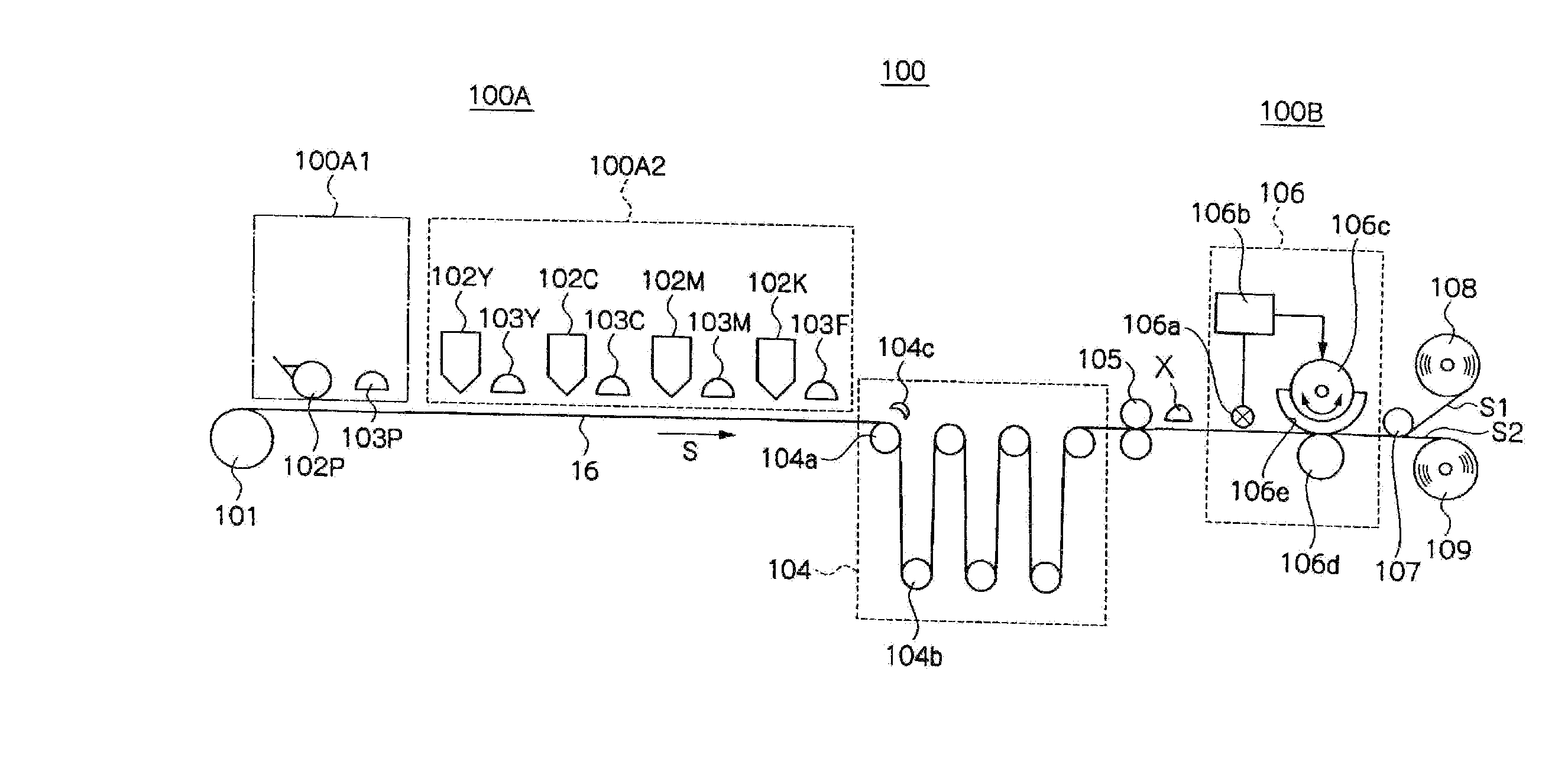
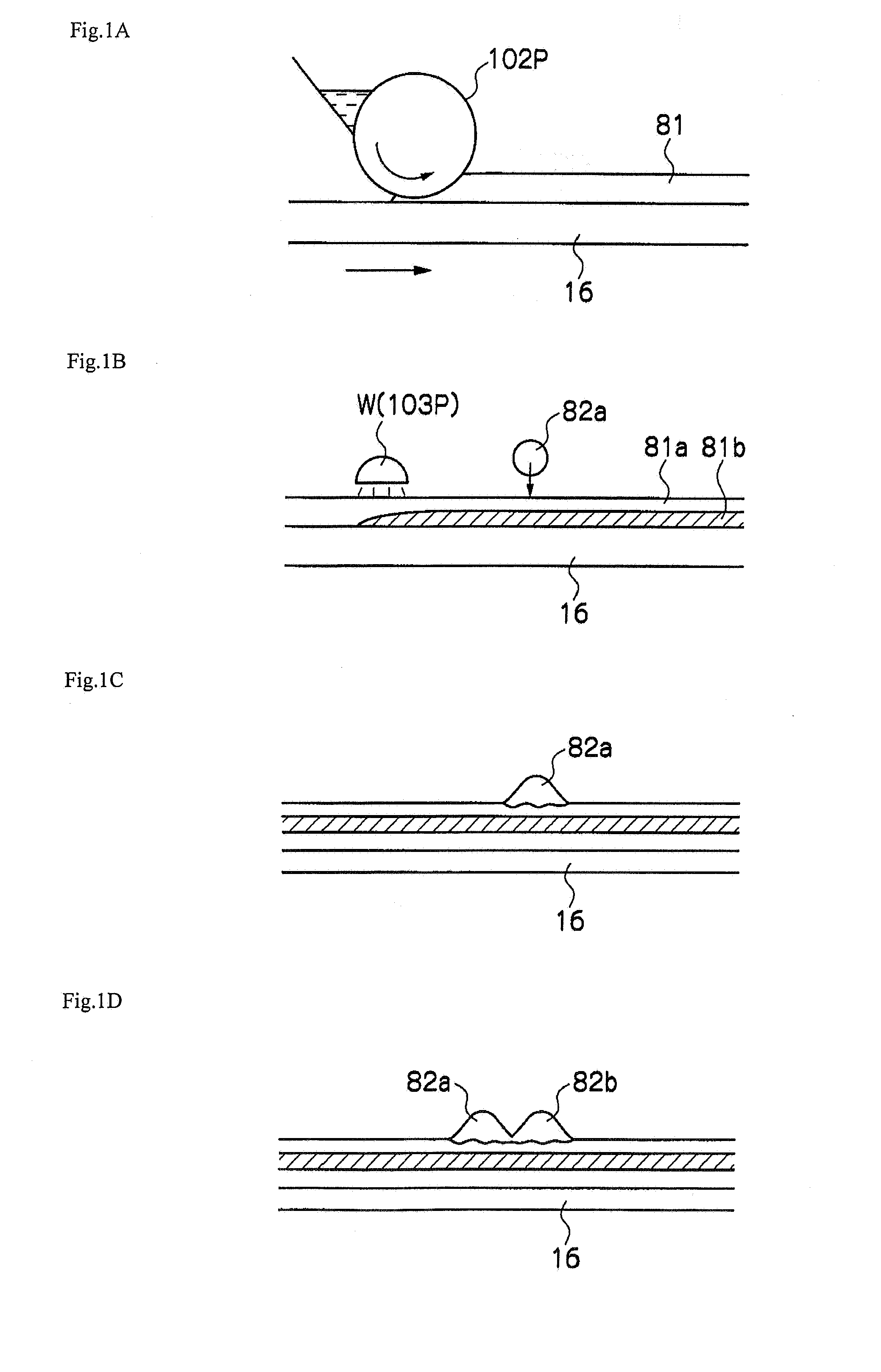
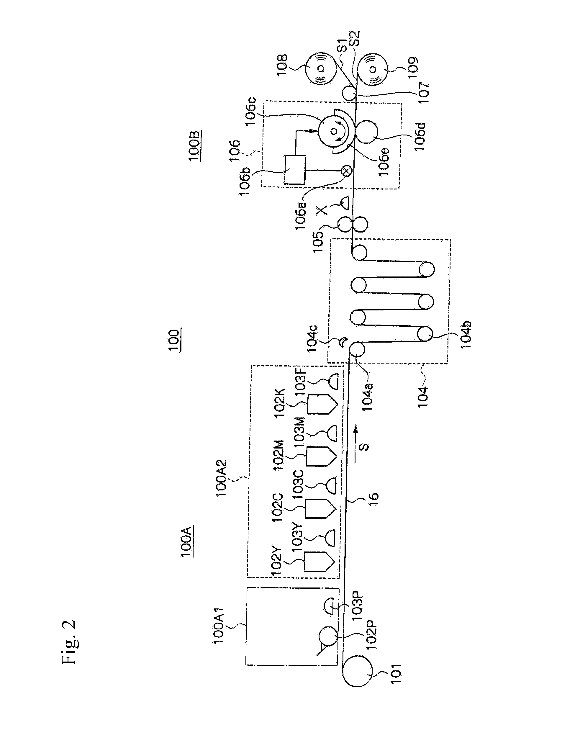
[0388] The image recording and the evaluation of the character quality of the reversal characters were performed using the same ink and undercoating liquid and in the same manner as Example 1, except the light source 103P for half-curing of the undercoating liquid was removed and the undercoating liquid and the yellow ink provided on the recording medium were half-cured at the same time by the pinning light source provided downstream of the yellow ink head with low visibility. The same results as that in Example 1 were also obtained in Example 3. By removing the light source 103P for half-curing of the undercoating liquid, bleeding was caused in the yellow ink. However, it does not lead to the deterioration in the image quality because of the low visibility of the yellow ink, and the cost for the light source could be reduced.


PUM

PropertyMeasurementUnit
surface temperatureaaaaaaaaaa
thicknessaaaaaaaaaa
densityaaaaaaaaaa

Abstract

The invention provides an ink jet recording method that records an image by ejecting, onto a recording medium, an ink that is cured by irradiation of an active energy ray, the method comprising: applying an undercoating liquid onto the recording medium; half-curing the undercoating liquid; and forming an image by ejecting an ink onto the half-cured undercoating liquid, and an ink jet recording device. According to the ink jet recording method in the invention, ink bleeding can be effectively suppressed when using any type of non-absorbing recording media, a high degree of uniformity in an image between various recording media can be obtained, and unevenness in line width or color caused by mixing between the liquid droplets can be suppressed.

Description

CROSS-REFERENCE TO RELATED APPLICATION [0001] This application claims priority under 35 USC 119 from Japanese Patent Application Nos. 2006-171732 and 2007-120744, the disclosure of which are incorporated by reference herein. BACKGROUND OF THE INVENTION [0002] 1. Field of the Invention [0003] The invention relates to an ink jet recording method and an ink jet recording device, and specifically relates to an ink jet recording method and an ink jet recording device favorably used for forming a high-quality image at high-speed. [0004] 2. Description of the Related Art [0005] An ink jet method of ejecting ink in the form of liquid droplets from an ink ejector has been used in various kinds of printers for the reasons of being compact and less expensive, capable of forming an image without contacting a recording medium, or the like. Among these ink jet methods, there are a piezo ink jet method utilizing deformation of piezoelectric elements to eject ink and a thermal ink jet method utiliz...

Claims


Application Information

Patent Timeline
Patent Type & Authority Applications(United States)
IPC IPC(8): B41J2/01B41M5/00C09D11/00C09D11/322C09D11/328C09D11/38
CPCB41J11/0015B41J11/002B41M7/0081B41M5/5209B41M5/0011B41J11/00214
Inventor NAKAZAWA, YUSUKEKASAI, SEISHIMAKUTA, TOSHIYUKI
Owner FUJIFILM CORP
Why Eureka
Try Eureka