Method and apparatus for angular-resolved spectroscopic lithography characterization

Active Publication Date: 2007-12-27
ASML NETHERLANDS BV
View PDF36 Cites 28 Cited by
  • Summary
  • Abstract
  • Description
  • Claims
  • Application Information

AI Technical Summary

Benefits of technology

[0007]It is desirable to provide an apparatus that will shorten the time taken for both p a

Problems solved by technology

This requires a lot of quickly moving parts and the alternating between the two polarizations incre

Method used


Image

  • Method and apparatus for angular-resolved spectroscopic lithography characterization
  • Method and apparatus for angular-resolved spectroscopic lithography characterization
  • Method and apparatus for angular-resolved spectroscopic lithography characterization

Examples


second embodiment

[0046]the present invention enables more parameters of the orthogonally polarized beams to be measured. FIG. 6 shows an example of an ellipsometric sensor (or an ellipsometer) based on the prior art. Ellipsometry is the measurement of the state of polarization of scattered light. Ellipsometry measures two parameters; the phase difference (Δ) between two differently polarized beams and an amplitude ratio (tan Ψ) of two polarized beams. With these two parameters, any polarization state of a purely polarized beam may be described. Specifically, if an incident beam has both s and p polarizations, the reflected beam will have reflectance coefficients Rp and Rs. The complex amplitudes of each polarization direction are represented by Ep and Es and are calculated as Rp.p and Rs.s, respectively. A is the phase difference between Ep and Es and tan Ψ is the ratio of Ep to Es. In other words,

Δ=arg(Ep−Es)   (1)

tan Ψ=Ep / Es   (2)

[0047]FIG. 7 shows the relationship between these two parameters. In...

first embodiment

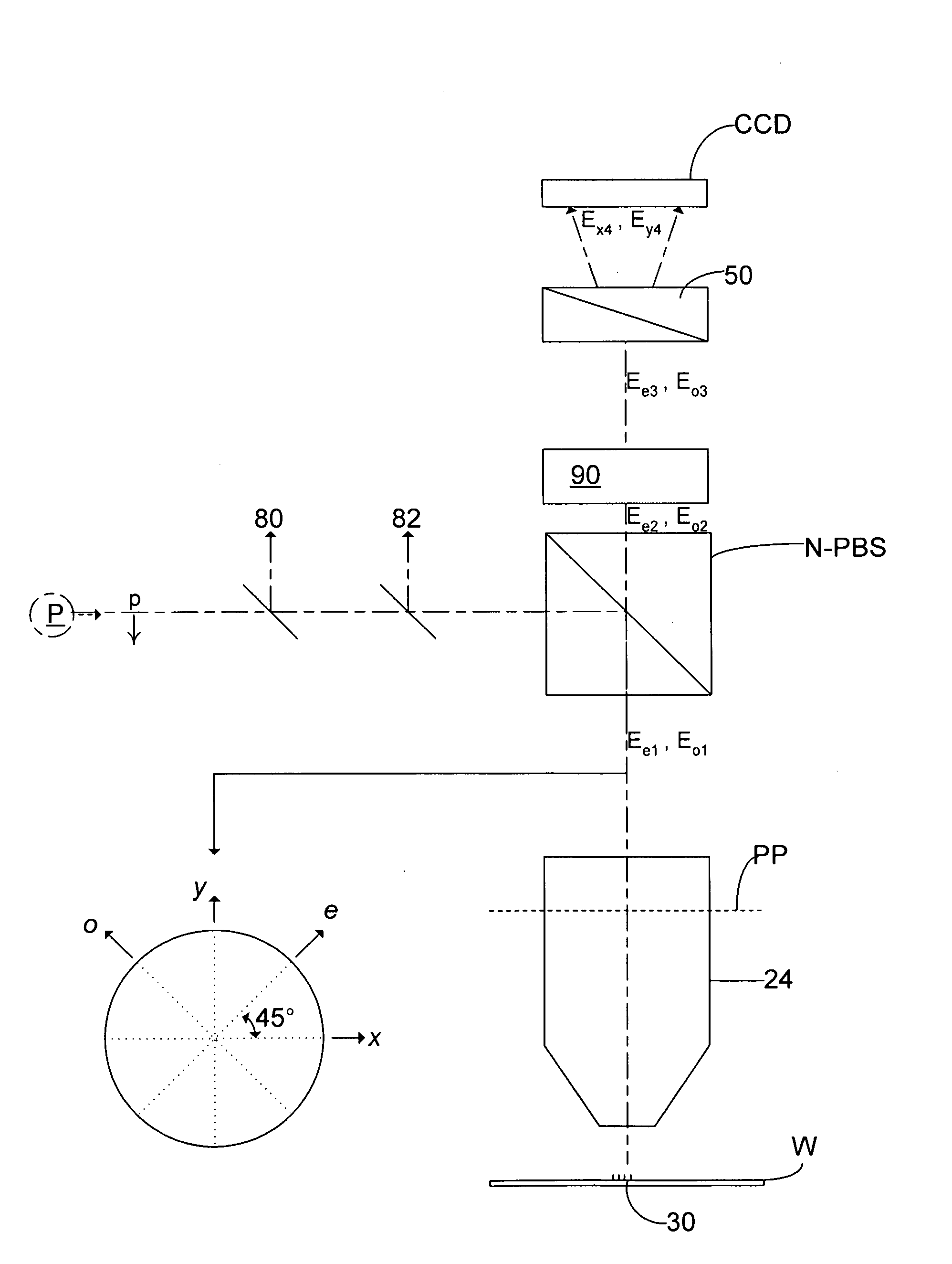
[0077]If the phase shifter 90 (with its modulation axis only the e-axis) is removed or turned to zero (i.e. with no phase shift), the apparatus of this invention is effectively created. In other words, this ellipsometer acts as the inspection apparatus of FIG. 4 if there is no phase shift.

[0078]Although specific reference may be made in this text to the use of lithographic apparatus in the manufacture of ICs, it should be understood that the lithographic apparatus described herein may have other applications, such as the manufacture of integrated optical systems, guidance and detection patterns for magnetic domain memories, flat-panel displays, liquid-crystal displays (LCDs), thin-film magnetic heads, etc. It should be appreciated that, in the context of such alternative applications, any use of the terms “wafer” or “die” herein may be considered as synonymous with the more general terms “substrate” or “target portion”, respectively. The substrate referred to herein may be processed...


PUM


Abstract

Simultaneous measurement of two orthogonally polarized beams upon diffraction from a substrate is done to determine properties of the substrate. Linearly polarized light sources with their radiation polarized in orthogonal directions are passed via two non-polarizing beamsplitters, one rotated by 90° with respect to the other. The combined beam is then diffracted off a substrate before being passed back through a non-polarizing beamsplitter and through a phase shifter and a Wollaston prism before being measured by a CCD camera. In this way, the phase and intensities for various phase steps of the two polarized beams may thereby be measured and the polarization state of the beams may be determined. If the phase shifter is turned to zero (i.e. with no phase shifting), the grating of the substrate has its parameters measured with TE and TM polarized light simultaneously with the same detector system.

Description

BACKGROUND OF THE INVENTION[0001]1. Field of the Invention[0002]The present invention relates to methods of inspection usable, for example, in the manufacture of devices by lithographic techniques and to methods of manufacturing devices using lithographic techniques, etching applications and thin-film metrology.[0003]2. Description of the Related Art[0004]A lithographic apparatus is a machine that applies a desired pattern onto a substrate, usually onto a target portion of the substrate. A lithographic apparatus can be used, for example, in the manufacture of integrated circuits (ICs). In that instance, a patterning device, which is alternatively referred to as a mask or a reticle, may be used to generate a circuit pattern to be formed on an individual layer of the IC. This pattern can be transferred onto a target portion (e.g. comprising part of, one, or several dies) on a substrate (e.g. a silicon wafer). Transfer of the pattern is typically via imaging onto a layer of radiation-s...

Claims


Application Information

Patent Timeline
IPC IPC(8): G01J4/00
CPCG01N21/21G03F7/7085G03F7/70616G01N21/956G03F7/2006H01L21/0274
Inventor KIERS, ANTOINE GASTON MARIEDEN BOEF, ARIE JEFFREYKEIJ, STEFAN CAROLUS JACOBUS ANTONIUS
Owner ASML NETHERLANDS BV
Why Eureka
Try Eureka