Magnetoresistive element and magnetic memory

a magnetic memory and magnetoresistive element technology, applied in the field of magnetoresistive element and magnetic memory, can solve the problems of dielectric breakdown and no operational reliability at a high voltage, and achieve the effect of ensuring the reliability of high voltage operation

Inactive Publication Date: 2007-12-27
KK TOSHIBA
View PDF5 Cites 218 Cited by
  • Summary
  • Abstract
  • Description
  • Claims
  • Application Information

AI Technical Summary

Benefits of technology

[0012]According to a first aspect of the present invention, there is provided a magnetoresistive element comprising: a first magnetic reference layer having a magnetization direction; a magnetic free layer having a magnetization direction which is changeable by being supplied with spin polarized electrons; a second magnetic reference layer having a magnetization direction; a first intermediate layer provided between the first magnetic reference layer and the magnetic free layer; and a second intermediate layer provided between the magnetic free layer and the second magnetic reference layer. The magnetic free layer and the first magnetic reference layer have directions of easy magnetization perpendicular or parallel to an in-plane direction. The first magnetic reference layer and the second magnetic reference layer have directions of easy magnetization perpendicular to each other.

Problems solved by technology

Hence, if the breakdown voltage of the tunnel barrier layer is not sufficiently high, the layer reaches a breakdown voltage Vbd and causes dielectric breakdown before obtaining the antiparallel magnetization arrangement.
Additionally, no operational reliability at a high voltage is ensured even without dielectric breakdown.

Method used


Image

  • Magnetoresistive element and magnetic memory
  • Magnetoresistive element and magnetic memory
  • Magnetoresistive element and magnetic memory

Examples


first embodiment

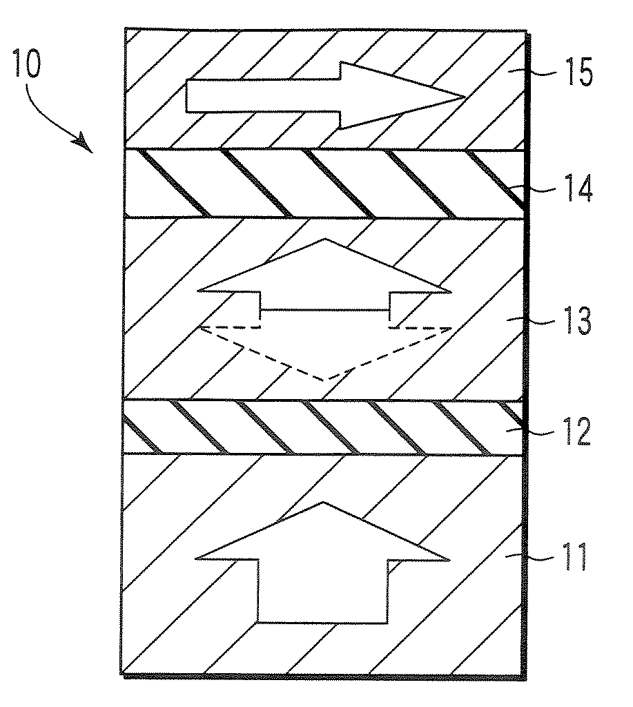
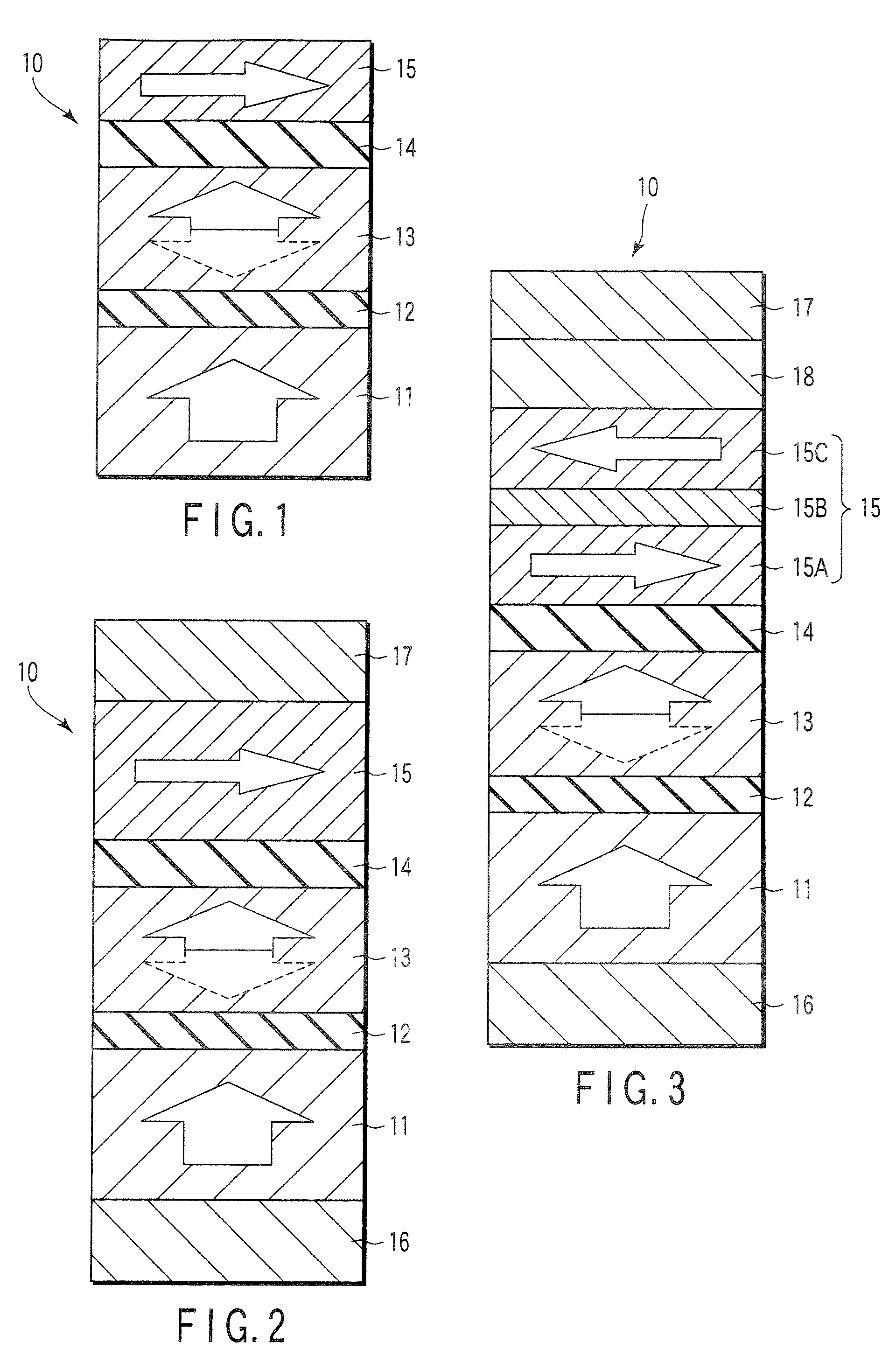
[0031]FIG. 1 shows the basic structure of the MTJ element 10 according to the first embodiment. Arrows in FIG. 1 indicate magnetization directions.

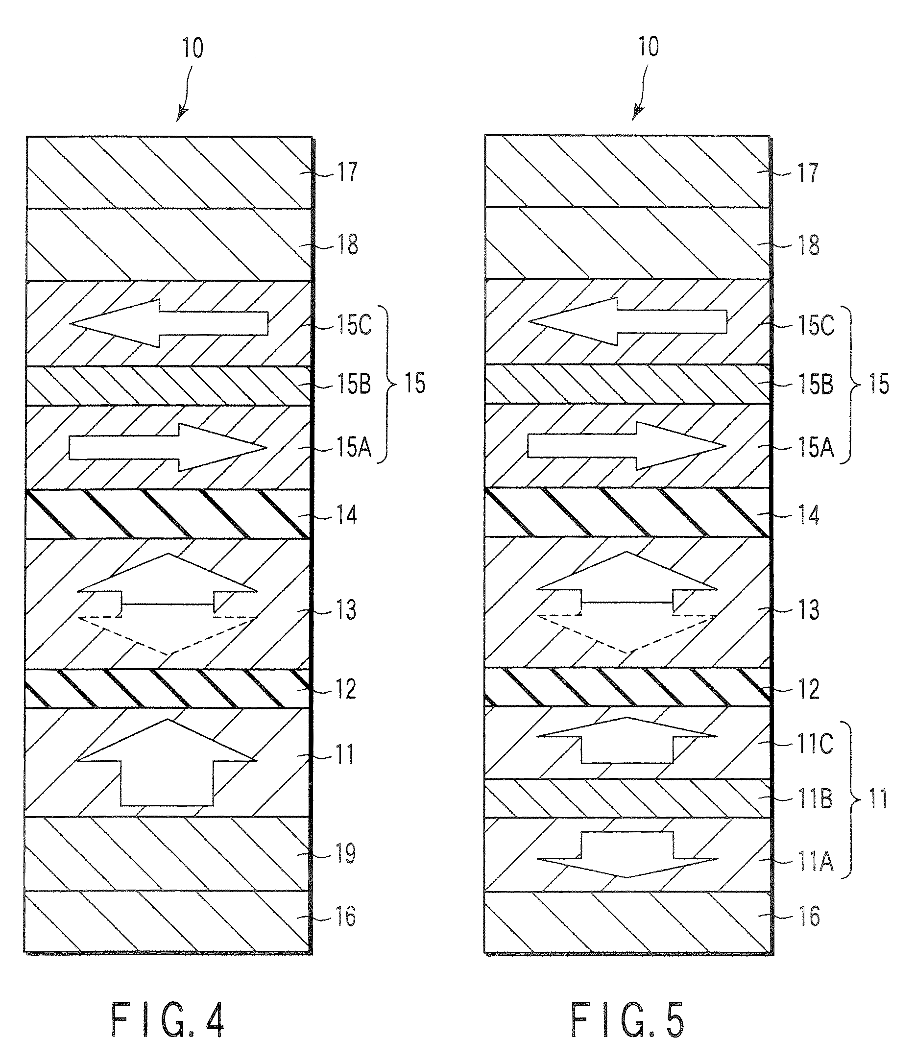
[0032]The MTJ element 10 has a layered structure of a first magnetic reference layer (pinned layer) 11, first intermediate layer 12, magnetic free layer (free layer) 13, second intermediate layer 14, and second magnetic reference layer (pinned layer) 15 which are stacked in this order. In this basic structure, the order of stacked layers may reverse.

[0033]The pinned layers 11 and 15 have fixed magnetization (or spin) directions. The magnetization direction of the free layer 13 changes (switches). The direction of easy magnetizations of the pinned layer 11 and free layer 13 are perpendicular to the film surface (or the in-plane direction) (this state will be referred to as “perpendicular magnetization” hereinafter). The direction of easy magnetization of the pinned layer 15 is parallel to the film surface (this state will be referred to as...

example 1

[0103]Ta5 / PtMn15 / CoFe2.5 / Ru0.85 / CoFe2.5 / Cu3(intermediate layer

[0104]14) / CoFeB0.5 / FePt(L10)2 / Fe0.5 / MgO0.75(intermediate layer

[0105]12) / CoFeB1 / FePt(L10)10 / Pt5 / Cr20 / MgO2 / CoFeB2 / Ta5 / / substrate

example 2

[0106]Ta5 / IrMn10 / CoFe2.5 / Ru0.85 / CoFe2.5 / Cu3(intermediate layer

[0107]14) / CoFeB0.5 / CoFeTb3 / CoFeB0.75 / MgO0.75(intermediate layer 12) / CoFeB2 / CoFeTb30 / Ru5 / Ta5 / / substrate


PUM


Abstract

A magnetoresistive includes a first magnetic reference layer having a fixed magnetization direction, a magnetic free layer having a magnetization direction which is changeable by being supplied with spin polarized electrons, a second magnetic reference layer having a fixed magnetization direction, a first intermediate layer provided between the first magnetic reference layer and the magnetic free layer, and a second intermediate layer provided between the magnetic free layer and the second magnetic reference layer. The magnetic free layer and the first magnetic reference layer have directions of easy magnetization perpendicular or parallel to an in-plane direction. The first magnetic reference layer and the second magnetic reference layer have directions of easy magnetization perpendicular to each other.

Description

CROSS-REFERENCE TO RELATED APPLICATIONS[0001]This application is based upon and claims the benefit of priority from prior Japanese Patent Application No. 2006-172844, filed Jun. 22, 2006, the entire contents of which are incorporated herein by reference.BACKGROUND OF THE INVENTION[0002]1. Field of the Invention[0003]The present invention relates to a magnetoresistive element and a magnetic memory and, for example, to a magnetoresistive element capable of recording data by supplying a current bidirectionally and a magnetic memory using the magnetoresistive element.[0004]2. Description of the Related Art[0005]There are recently proposed a number of solid-state memories that record data on the basis of a new principle. Among them all, a magnetoresistive random access memory (MRAM) using a tunneling magnetoresistive (TMR) effect is especially receiving a great deal of attention as a solid-state magnetic memory. As a characteristic feature, an MRAM stores data in accordance with the magn...

Claims


Application Information

Patent Timeline
Patent Type & Authority Applications(United States)
IPC IPC(8): G11C11/00
CPCB82Y25/00G11C11/16H01F10/325H01F10/3254H01F10/123H01L27/226H01L43/08H01F10/3286H01F10/329H01F10/3272H10B61/20H10N50/10G11C11/15
Inventor YOSHIKAWA, MASATOSHIKAI, TADASHINAGASE, TOSHIHIKOKISHI, TATSUYAYODA, HIROAKI
Owner KK TOSHIBA
Why Eureka
Try Eureka