Fuel Cell
a fuel cell and hydrogen permeable metal technology, applied in the field of fuel cells, can solve the problems of deteriorating the performance of the fuel cell, lowering the durability of deteriorating the hydrogen permeable metal layer, so as to prevent the deteriorating performance and lowering durability of the fuel cell
- Summary
- Abstract
- Description
- Claims
- Application Information
AI Technical Summary
Benefits of technology
Problems solved by technology
Method used
Image
Examples
first embodiment
A. Structure of Fuel Cell in First Embodiment
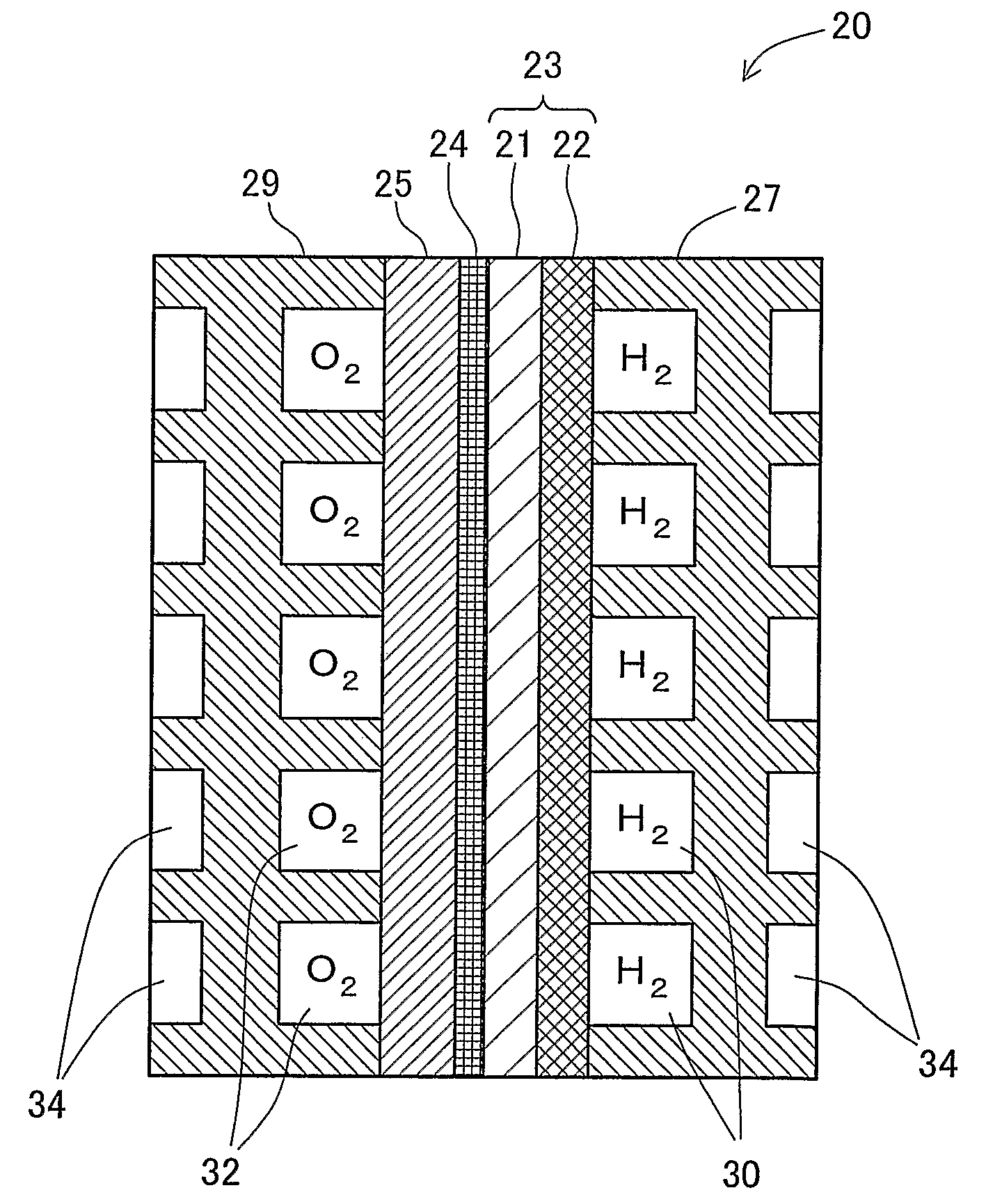
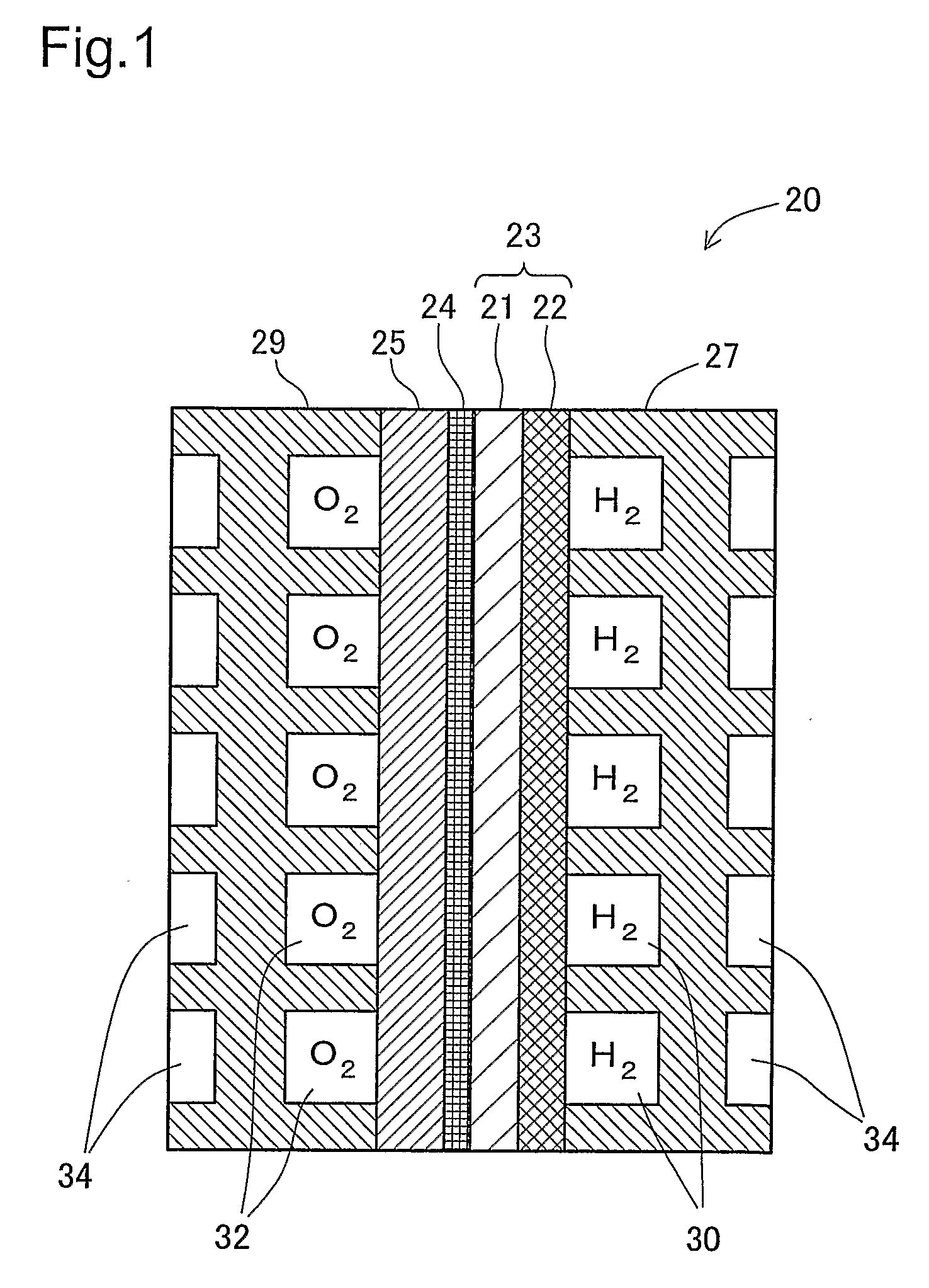
[0056]FIG. 1 is a sectional view schematically illustrating the structure of a unit fuel cell 20 as a unit of fuel cells in a first embodiment of the invention. The unit fuel cell 20 has an electrolyte module 23 including a hydrogen permeable metal layer 22 and an electrolyte layer 21, a catalyst layer 24 formed on the electrolyte layer 21, a cathode 25 formed on the catalyst layer 24, and a pair of gas separators 27 and 29 located across the assembly of this layered structure. In-cell fuel gas conduits 30 are defined by and formed between the gas separator 27 and the hydrogen permeable metal layer 22 to allow a flow of a hydrogen-containing fuel gas. Similarly, in-cell oxidizing gas conduits 32 are defined by and formed between the gas separator 29 and the cathode 25 to allow a flow of an oxygen-containing oxidizing gas. The fuel cells of the invention have a stack structure including a number of the unit fuel cells 20 shown in FIG. 1. C...
second embodiment
D-1. Second Embodiment
[0076]FIG. 10 is a sectional view schematically illustrating the structure of a fuel cell in a second embodiment of the invention. The gas separators 27 and 29 are omitted from the illustration, and FIG. 10 shows only the structure of an electrolyte module and a cathode 125 included in the fuel cell of the second embodiment. The fuel cell of the second embodiment has a similar structure to that of the fuel cell 20 of the first embodiment, except that the catalyst layer 24 and the cathode 25 are replaced by the cathode 125. The cathode 125 is a thin metal membrane of a noble metal having catalytic activity and functioning as the catalyst of the electrochemical reaction, for example, Pt, a Pt alloy, Pd, or a Pd alloy. When the selected material for the cathode 125 is a hydrogen impermeable metal, such as Pt, the cathode 125 is formed sufficiently thin to ensure the required gas permeability. The cathode 125 may be formed on the electrolyte layer 21 deposited over...
third embodiment
D-2. Third Embodiment
[0079]FIG. 12 is a sectional view schematically illustrating the structure of a fuel cell in a third embodiment of the invention. The fuel cell of the third embodiment has a similar structure to that of the fuel cell 20 of the first embodiment, except that the hydrogen permeable metal layer 22 is replaced by another hydrogen permeable layer 222. The gas separators 27 and 29 are omitted from the illustration of FIG. 12 as in the illustration of FIG. 10.
[0080] The hydrogen permeable metal layer 222 is made of a hydrogen permeable metal similarly to the hydrogen permeable metal layer 22 of the first embodiment but has a varying patterned indented surface structure. The varying patterned indented surface structure of the hydrogen permeable metal layer 222 is designed to vary the effective surface area of the electrode in an identical plane. Like the cathode 125 of the second embodiment, any adequate technique, for example, argon ion etching or shot blast, is applie...
PUM
| Property | Measurement | Unit |
|---|---|---|
| operating temperature | aaaaa | aaaaa |
| temperature | aaaaa | aaaaa |
| temperature | aaaaa | aaaaa |
Abstract
Description
Claims
Application Information
 - R&D
- Intellectual Property
- Life Sciences
- Materials
- Tech Scout
- Unparalleled Data Quality
- Higher Quality Content
- 60% Fewer Hallucinations
Browse by: Latest US Patents, China's latest patents, Technical Efficacy Thesaurus, Application Domain, Technology Topic, Popular Technical Reports.
© 2025 PatSnap. All rights reserved.Legal|Privacy policy|Modern Slavery Act Transparency Statement|Sitemap|About US| Contact US: help@patsnap.com


