Induced-charge electro-osmotic microfluidic devices

a microfluidic device and electro-osmotic technology, applied in the direction of fluid pressure measurement, liquid/fluent solid measurement, peptide measurement, etc., can solve the problems of traditional pressure-driven flow that cannot scale well with miniaturization, capillary electro-osmosis, with or without field-effect flow control, and is not ideal for certain applications

Inactive Publication Date: 2008-01-03
MASSACHUSETTS INST OF TECH
View PDF18 Cites 31 Cited by
  • Summary
  • Abstract
  • Description
  • Claims
  • Application Information

AI Technical Summary

Benefits of technology

[0019] at least one pumping element comprising two or more parallel-positioned or interdigitated electrodes positioned therebetween; wherein electrodes in said pumping element vary in height with respect to each other, said background electrodes, or a combination thereof.
[0020] In one embodiment, the pumping element is held at a fixed potential, relative to that of the background electrodes. In another embodiment, at least one electrode in the pumping element is grounded to one of the background electrodes. In another embodiment, the microchannel comprises multiple background electrodes, multiple pumping units placed therebetween, or a combination thereof.

Problems solved by technology

This typically takes from seconds to minutes—far too slow for envisioned applications.
Traditional pressure-driven flows do not scale well with miniaturization, due to large viscous stresses, so other pumping techniques have been explored.
Capillary electro-osmosis, with or without field-effect flow control, however, is not ideal for certain microfluidic applications, since the electric field is applied down the channel, a large voltage is required, e.g. 100 Volts across a 1 cm device to generate typical fields of 100 V / cm.
Since electro-osmosis is linear in the applied field, a direct current must be sustained through Faradaic electrochemical reactions at the electrodes generating the field, which can produce gas bubbles, electrode degradation / dissolution, hydrodynamic instability, and sample contamination.
While existing ACEO pumps operate at much lower power (mA) and lower voltage (Volt) than microfluidic pumps based on linear electro-osmosis, nonetheless, current ACEO devices are somewhat inefficient for long-range pumping, and more general flow topologies for simultaneous mixing and pumping have not been developed.

Method used


Image

  • Induced-charge electro-osmotic microfluidic devices
  • Induced-charge electro-osmotic microfluidic devices
  • Induced-charge electro-osmotic microfluidic devices

Examples


example 1

General Schematic for a Device Comprising Induced-Charge Electro-Osmotically Driven Microfluidic Pumps

[0333] It is possible to create many permutations of a device comprising induced-charge electro-osmotically driven microfluidic mixers or pumps, or a combination thereof, as will be appreciated by one skilled in the art.

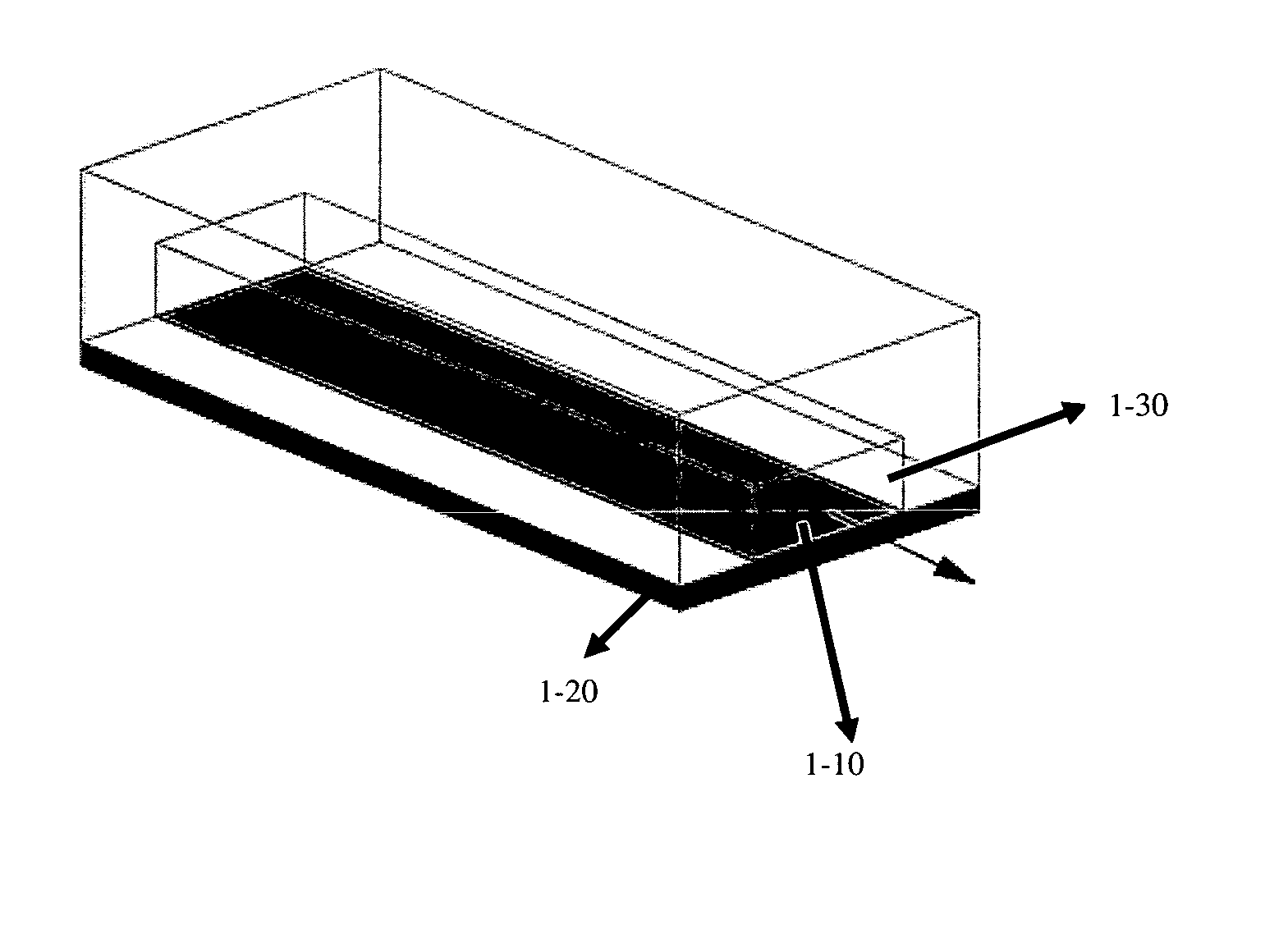
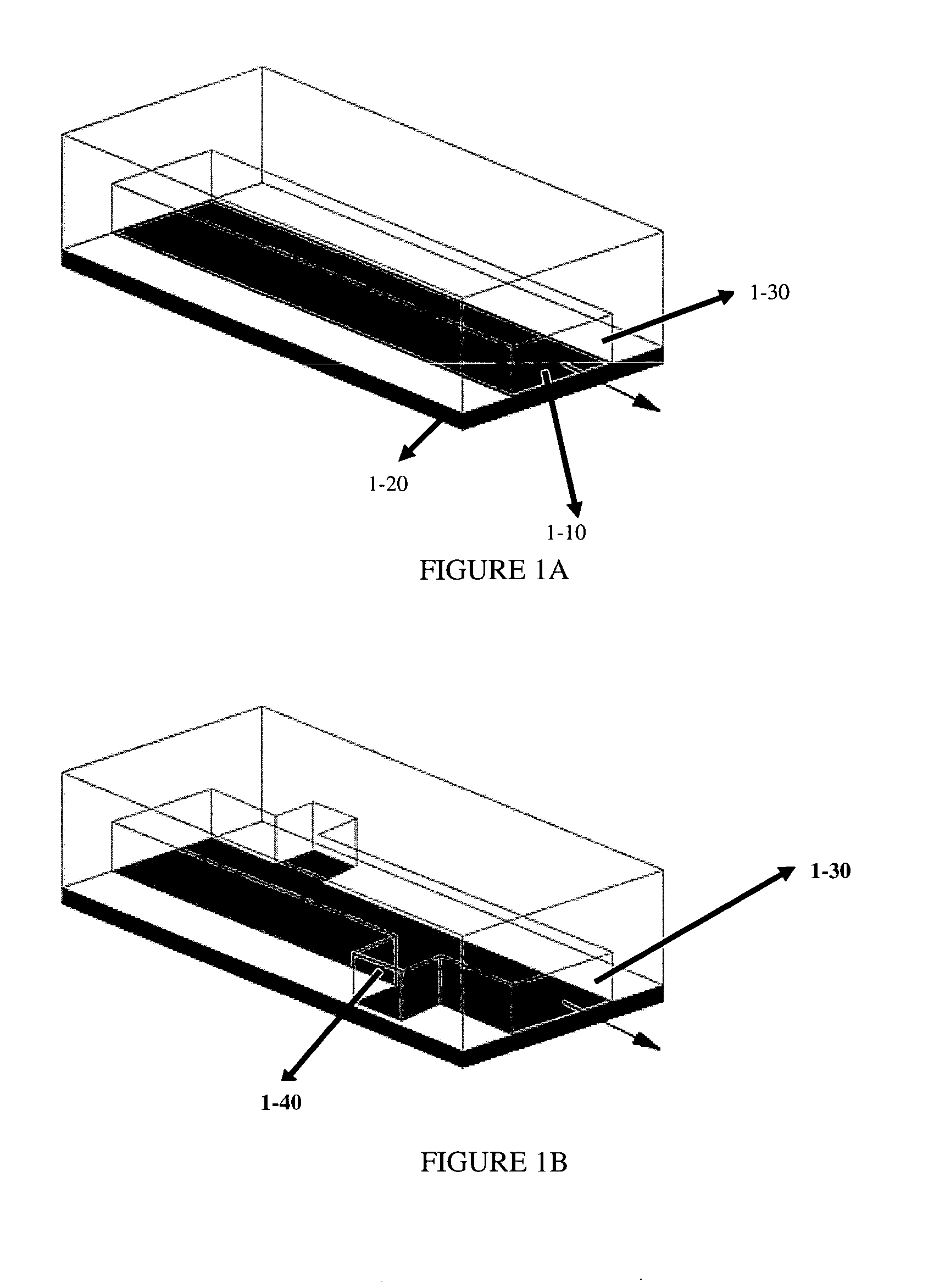
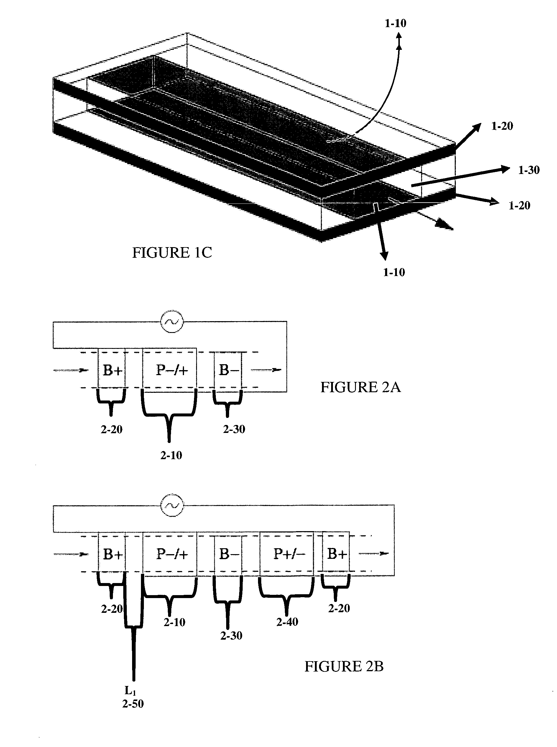
[0334] A general schematic of microfluidic devices for use in this invention is depicted in FIG. 1. In this embodiment, metal electrodes (1-10) are patterned onto a substrate (1-20), typically glass or silicon, to form an electrokinetic “pump”. Fluid is pumped down a microfluidic channel (1-30), which may be formed by a molded-polymer (e.g. PDMS) cap. Typical dimensions for the cross section of the microchannel are of order 1-1000 microns in height and 10-10000 microns in width.

[0335] The microfluidic channels may be straight (FIG. 1A) or have recessed regions (1-40) (FIG. 1B). In such channels designed for biological or chemical sensing, the upper surface and sid...

example 2

Circuitry and Spatial Layout for Some Devices of this Invention

[0339] The electrical circuitry and general spatial layout are shown in FIG. 2. According to this embodiment, (FIG. 2A) two background electrodes, B+ (2-20) and B− (2-30), apply an AC electric field across a single primary pumping element, P− / + (2-10), which consists of interlaced electrodes connected to B+ and B− as described further, hereinbelow. Another embodiment comprises successive positioning of the elements, for example as depicted in FIG. 2B, where a pumping element with the opposite symmetry, P+ / − (240), is positioned in the device, in a repeating pattern, for example B+, P− / +, B−, P+ / −, etc.

[0340] According to these embodiments, fluid pumps from left to right, as indicated by the arrows in FIG. 2. When the background electric field extends from B+ to B−, the P− / +pumping element causes pumping in the same direction since the induced double layer charge is predominantly positive, due to a larger surface area a...

example 3

Pumping Elements Having Electrodes of Different Heights May Increase Flow Rate

[0349] In some embodiments of the invention, the flow rate is increased by altering the geometry of the various parts, such that the slipping surfaces work together to pump fluid in a single direction. According to this embodiment, raising all the surfaces pumping in the desired direction (and / or lowering the others) serves to “bury” reverse convection rolls. If the height difference is comparable to the width of the buried electrodes, the reverse convection rolls turn over near the upper surface and provide an effective “conveyor belt” for the primary pumping flow over the raised electrodes. In this way, the reverse flows actually aid the primary pumping flow, rather than hinder it; the resulting flow may exceed that of designs where the reverse flow is replaced by flat no-slip surfaces in a planar geometry.

[0350] For example, with reference to the pumping element in FIG. 5A, consisting of planar interl...


PUM

PropertyMeasurementUnit
widthsaaaaaaaaaa
widthsaaaaaaaaaa
AC voltageaaaaaaaaaa

Abstract

This invention provides devices and apparatuses comprising the same, for efficient pumping and/or mixing of relatively small volumes of fluid. Such devices utilize nonlinear electrokinetics as a primary mechanism for driving fluid flow. Methods of cellular analysis and high-throughput, multi-step product formation using devices of this invention are described.

Description

CROSS REFERENCE TO RELATED APPLICATIONS [0001] This application claims the benefit of U.S. Provisional Application Ser. No. 60 / 764,358, filed Feb. 2, 2006, which is hereby incorporated by reference in its entirety.GOVERNMENT SUPPORT [0002] This invention was produced with Government support under Grant Number DAAD-19-02-D-0002US awarded by the Army Research Office. The government has certain rights in the invention.FIELD OF THE INVENTION [0003] The invention relates to the fields of microfluidics, micro-total-analysis systems (μTAS) and micro-electro-mechanical systems (MEMS), in particular microfluidic pumps and mixers driven by induced-charge electro-osmosis. BACKGROUND OF THE INVENTION [0004] The ability to transport fluids in micron-sized channels is essential for many emerging technologies, such as in vivo drug delivery devices, micro-electro-mechanical systems (MEMS), and micro-total-analysis systems (μTAS). New methods for the rapid mixing of non-homogeneous fluids in micron-...

Claims


Application Information

Patent Timeline
Patent Type & Authority Applications(United States)
IPC IPC(8): G01N27/26C25B15/00C25B9/00
CPCG01N27/26
Inventor BAZANT, MARTIN Z.BEN, YUXINGLEVITAN, JEREMYURBANSKI, JOHN-PAUL
Owner MASSACHUSETTS INST OF TECH
Why Eureka
Try Eureka