Heat Dissipation Structure With Aligned Carbon Nanotube Arrays and Methods for Manufacturing And Use

a carbon nanotube and array technology, applied in chemical/physical/physical-chemical processes, chemical apparatus and processes, energy-based chemical/physical/physical-chemical processes, etc., can solve the problem of significantly limiting the advantage of heat conduction by carbon nanotubes, thermal interface materials with randomly directed carbon nanotubes dispersed in epoxy resins or other matrix materials, and inability to meet the increasing requirement of heat dissipation from a small area. , to achieve the effect of reducing th

Active Publication Date: 2008-01-03
THE HONG KONG UNIV OF SCI & TECH
View PDF24 Cites 35 Cited by
  • Summary
  • Abstract
  • Description
  • Claims
  • Application Information

AI Technical Summary

Benefits of technology

[0007] The present inventions provide a new way to use high thermal conductivity carbon nanotube (CNT) arrays. To avoid the process incompatibility of carbon nanotube growth and device fabrication the aligned CNT arrays are formed on heat dissipation structure surfaces instead of a heat source surface. To simplify the fabrication process and decrease the cost, aligned CNT arrays are grown on both sides of heat dissipation structure surfaces at one time. The heat dissipation structure with CNT arrays are used to directly dissipate heat from a heat source to a cooler. The CNT arrays in between a heat source and a cooler are used as thermal interface material extending and dissipate heat directly from a heat source surface to a cooler surface. The CNT arrays exposed to the environment instead of being in between a heat source and a solid cooler serve as fins to enlarge heat dissipation area and improve thermal convection.
[0008] In various embodiments, the disclosed inventions provide several of the following advantages:

Problems solved by technology

Unfortunately, conventional thermal interface materials, such as thermal grease thermal adhesives, phase change materials, etc., cannot meet the increasing requirement of the heat dissipation from a small area.
However thermal interface materials with randomly directed carbon nanotubes dispersed in epoxy resins or other matrix materials does not perform well because of the highly anisotropic nature of the thermal conduction by carbon nanotubes.
However, the phonon heat transfer modes in matrix materials and carbon nanotubes are not compatible, which significantly limits the advantage of heat conduction by carbon nanotube.
In addition, solidified matrix material is less flexible to fill in the uneven surfaces of heat source and heat sink.
However, the processes are not compatible for carbon nanotubes synthesis and device fabrication.
If carbon nanotubes are grown before device fabrication, the decreased wafer cleanliness and ability to protect carbon nanotubes will make it difficult to conduct device fabrication using normal processes and equipments.
Alternatively, if a device is fabricated before carbon nanotubes growth, the high temperature required by growing carbon nanotubes will damage the device or increasing the device cost by changing the processes and materials.
However, it is very difficult to form a very thin layer so that the tips of carbon nanotubes can still make contact with the heat source surface.
As a result, there is actually another added layer with additional thermal resistance, which reduces the thermal performance of the thermal management solution.
However, it is difficult for carbon nanotubes from any surface to extend directly to the other surface.

Method used


Image

  • Heat Dissipation Structure With Aligned Carbon Nanotube Arrays and Methods for Manufacturing And Use
  • Heat Dissipation Structure With Aligned Carbon Nanotube Arrays and Methods for Manufacturing And Use
  • Heat Dissipation Structure With Aligned Carbon Nanotube Arrays and Methods for Manufacturing And Use

Examples


Embodiment Construction

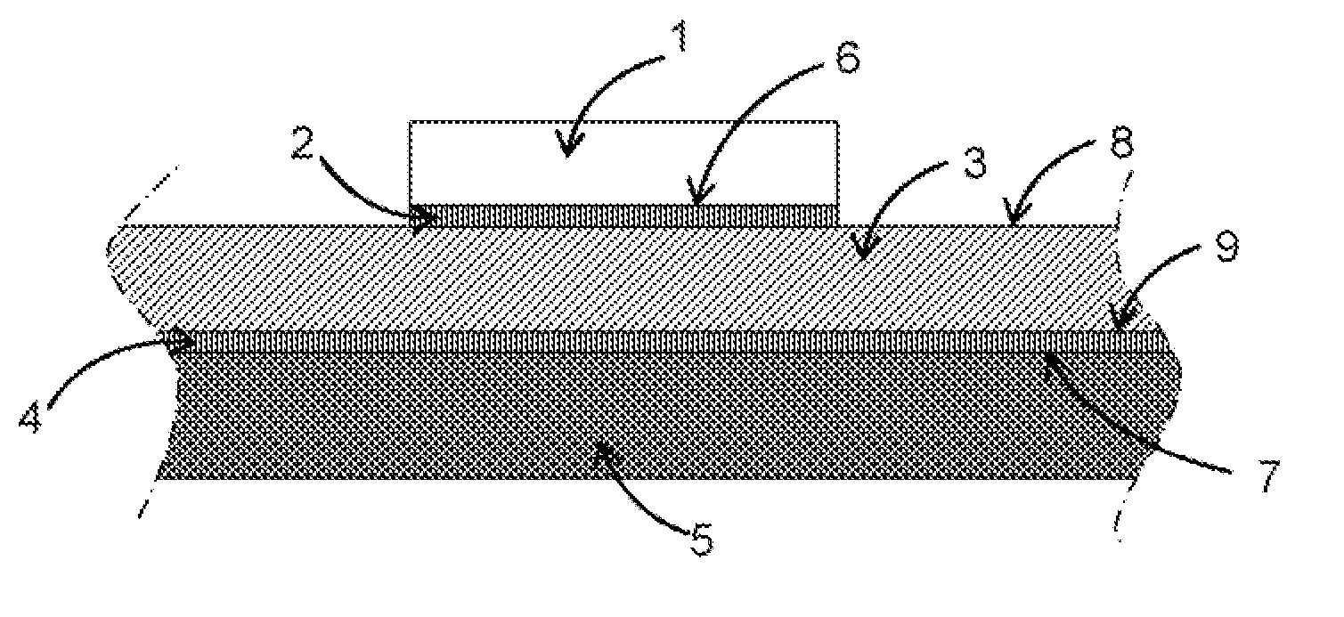
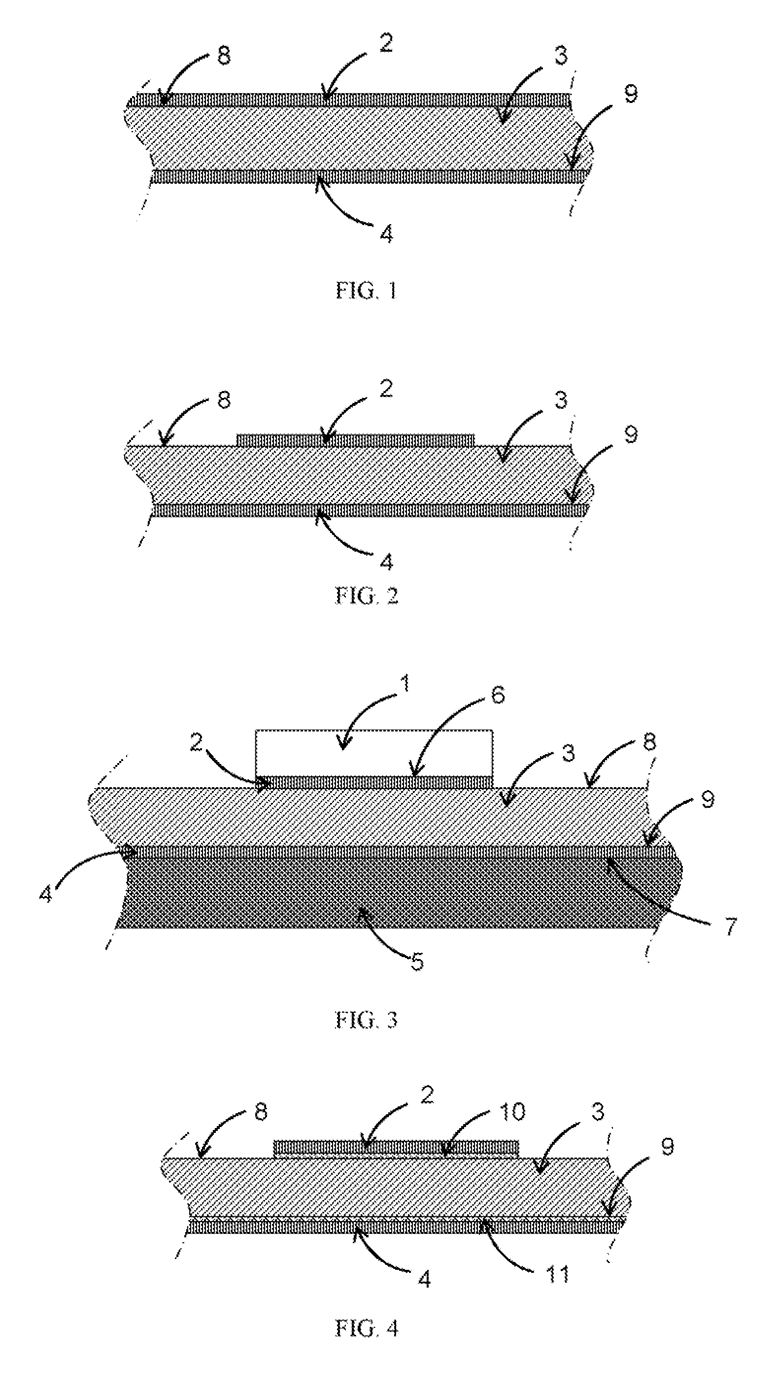
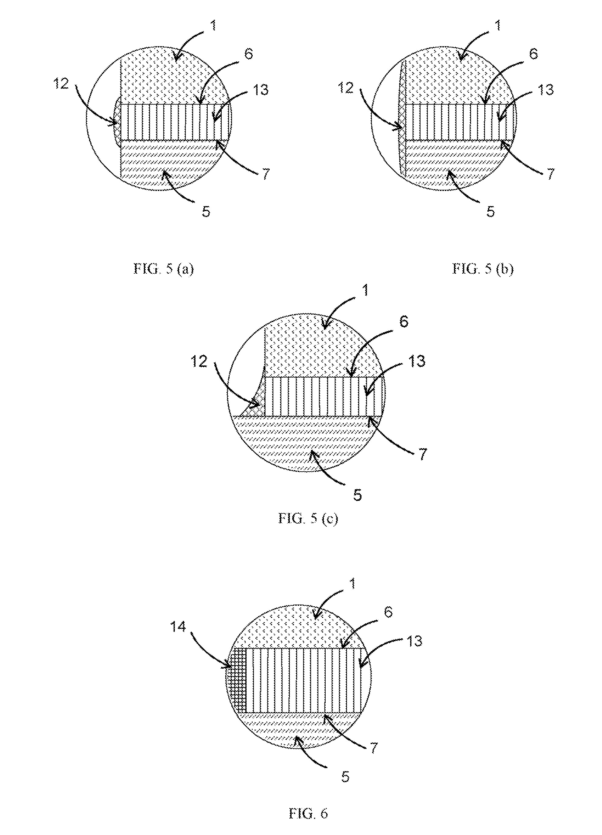
[0030] The present application discloses embodiments of a heat dissipation structure with aligned carbon nanotube (CNT) arrays on both sides that serve as thermal interface material or heat dissipation fins for enlarging the thermal convection area and methods for manufacturing it. Details are set forth to provide a thorough understanding of the embodiments of the present inventions with the help of the drawings but not limited to. The features, structures, materials, and characteristics of the inventions can be combined in any suitable manner in one or more embodiments.

[0031] In one embodiment, to simplify the fabrication process and decrease the cost, the aligned CNT arrays are grown on both sides of heat dissipation structure surfaces at one time. No catalyst is predeposited on heat dissipation structure surfaces or pretreated for growing. Sublimed catalyst, such as Ferrocence, is used as raw material. In addition, carbon nanotubes are synthesized on heat dissipation structure s...


PUM

PropertyMeasurementUnit
diameteraaaaaaaaaa
temperatureaaaaaaaaaa

Abstract

A heat dissipation structure with aligned carbon nanotube arrays formed on both sides. The carbon nanotube arrays in between a heat source and a cooler are used as thermal interface material extending and dissipating heat directly from a heat source surface to a cooler surface. In some embodiments, an adhesive material can be used to dispense around carbon nanotube arrays and assemble the heat dissipation structure in between a heat source and a cooler. In some other embodiments, carbon nanotube arrays are formed on at least one of a heat source surface and a cooler surface and connect them together by further growing. The carbon nanotube arrays can be exposed to the environment instead of being in between a heat source and a solid cooler, and can serve as fins to enlarge heat dissipation area and improve thermal convection.

Description

CROSS-REFERENCE TO OTHER APPLICATION [0001] The present application claims priority under 35 U.S.C. §119(e) of U.S. Patent Application No. 60 / 808,433, filed May 26, 2006, and entitled Heat Dissipation Structure with Carbon Nanotube Arrays and Method for Manufacturing the Same.BACKGROUND OF THE INVENTIONS [0002] The present application generally relates to thermal management solutions, and more specifically to heat dissipation structures using aligned carbon nanotube arrays, and to methods of fabricating such a heat dissipation structure and applying it to a package. [0003] With the development of microelectronic systems, for example, high brightness light emitting diode (HB-LED) for solid-state lighting, significant challenges of thermal management have to be faced to meet the increasing requirements of smaller profile, higher performance and longer product life time. More heat generated by devices needs to be effectively dissipated from a smaller area. Several kinds of heat sink ar...

Claims


Application Information

Patent Timeline
Patent Type & Authority Applications(United States)
IPC IPC(8): H01L23/373C01B31/02
CPCH01L23/373Y10S977/742H01L2924/0002H01L2924/00
Inventor YUEN, MATTHEW MING FAIZHANG, KAI
Owner THE HONG KONG UNIV OF SCI & TECH
Why Eureka
Try Eureka