Load drive controller and control system

a technology of controller and control system, applied in the direction of circuit-breaking switches, protective switch details, transportation and packaging, etc., can solve the problems of affecting users using the system employing the control unit, the control unit itself is shut down, and the entire system is terminated, so as to prevent overheating of the switching element and increase the temperature of the heat generating member

Inactive Publication Date: 2008-01-03
DENSO CORP
View PDF4 Cites 17 Cited by
  • Summary
  • Abstract
  • Description
  • Claims
  • Application Information

AI Technical Summary

Benefits of technology

[0015]According to another aspect of the present invention, a load drive control system includes a heat generating member which generates heat when current is supplied thereto, a switching element for switching energization of the heat generating member from a power source, a driving portion for driving the switching element to be turned on or off, a temperature adjustment portion for adjusting a temperature of the heat generating member by absorbing heat generated from the heat generating member, a temperature detection portion located to detect a physical quantity of a level corresponding to a temperature of the switching element, a protection function portion which outputs an abnormality signal corresponding to an overheated state of the switching element when the physical quantity detected by the temperature detection portion exceeds a value at which the switching element is estimated to be in the overheated state, and a control portion for causing the heat generating member to generate heat by driving the switching element via the driving portion. Furthermore, the control portion controls the temperature adjustment portion so as to increase the temperature of the heat generating member when the abnormality signal is input from the protection function portion. Accordingly, the system can effectively prevent overheating of the switching element without stopping the entire system.

Problems solved by technology

In such a control unit, the operation member is actuated when the temperature on the drive transistor exceeds a high temperature that is unacceptable.
Although the above-described known technique can protect the drive transistor from overheating, the current passing through the drive transistor is completely stopped, thereby leading to shutdown of the control unit itself.
In other words, this leads to termination of the function of the entire system using the control unit, thereby affecting users using the system employing the control unit.

Method used


Image

  • Load drive controller and control system
  • Load drive controller and control system
  • Load drive controller and control system

Examples


first embodiment

[0028]A first embodiment of the present invention will be described below with reference to the accompanying drawings. A load drive controller as described in this embodiment is used, for example, for control of air conditioning of a vehicle, so as to protect a drive transistor for energizing and driving a PTC from overheating.

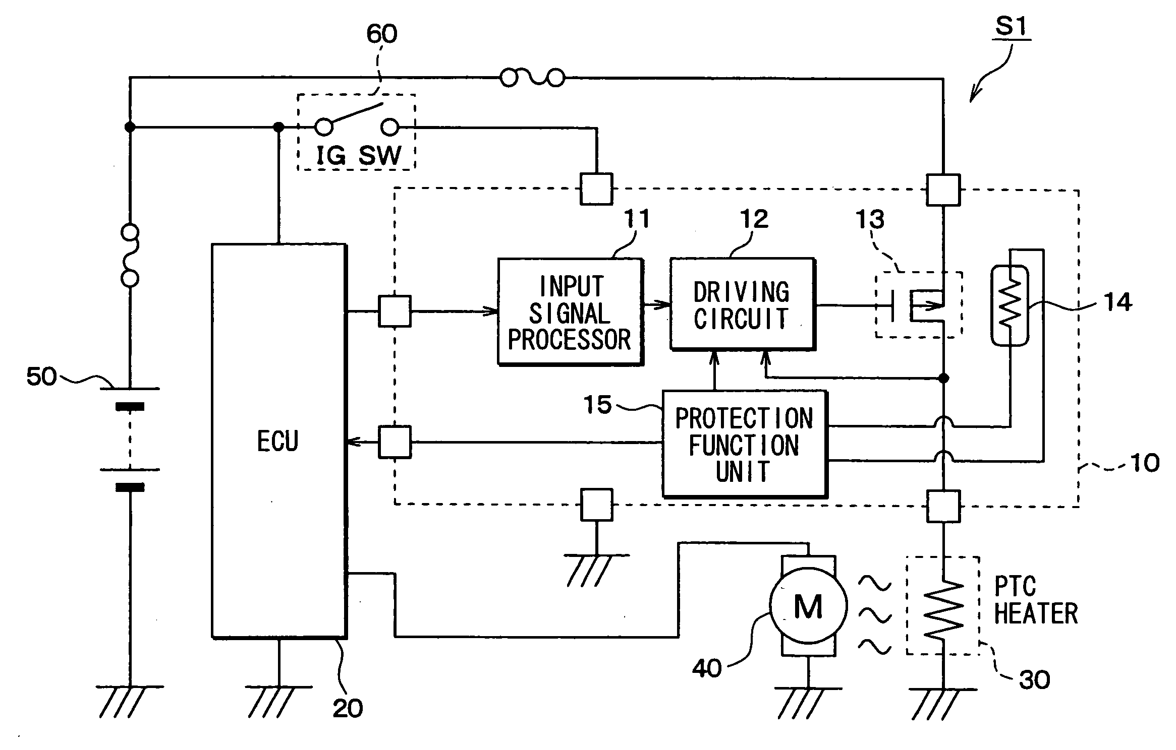
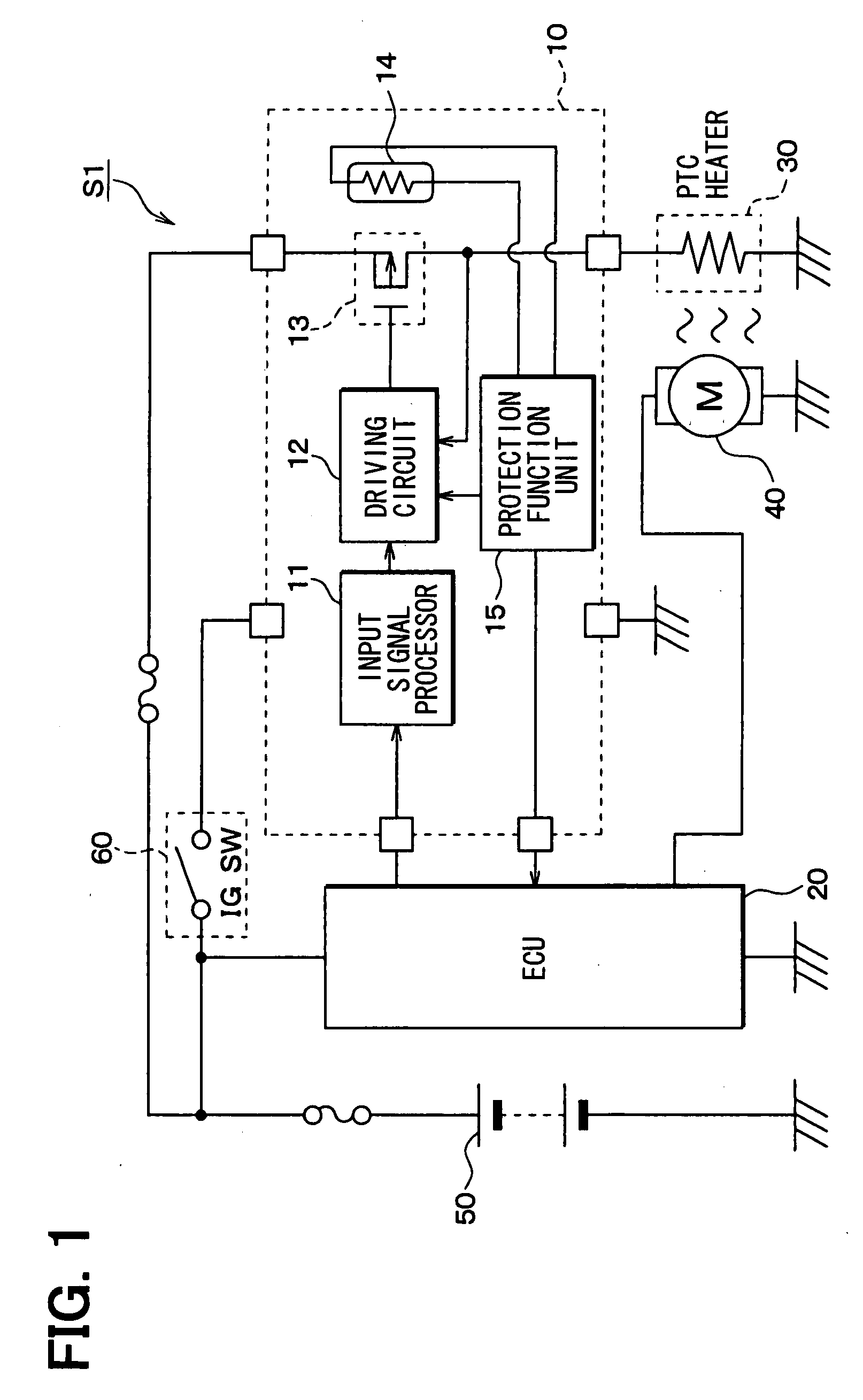
[0029]FIG. 1 shows a configuration diagram of a load drive control system according to the first embodiment of the present invention. As shown in the figure, the load drive control system S1 includes a load drive controller 10, an ECU 20 (control means), a PTC heater 30 (heat generating member), and a blower motor (temperature adjustment portion) 40.

[0030]The load drive controller 10 and the ECU 20 are actuated by being energized by a power source 50, and the PTC heater 30 is actuated by being energized by the power source 50 via the load drive controller 10. The load drive controller 10 is energized by the power source 50 when a vehicle ignition switch 60 is ...

second embodiment

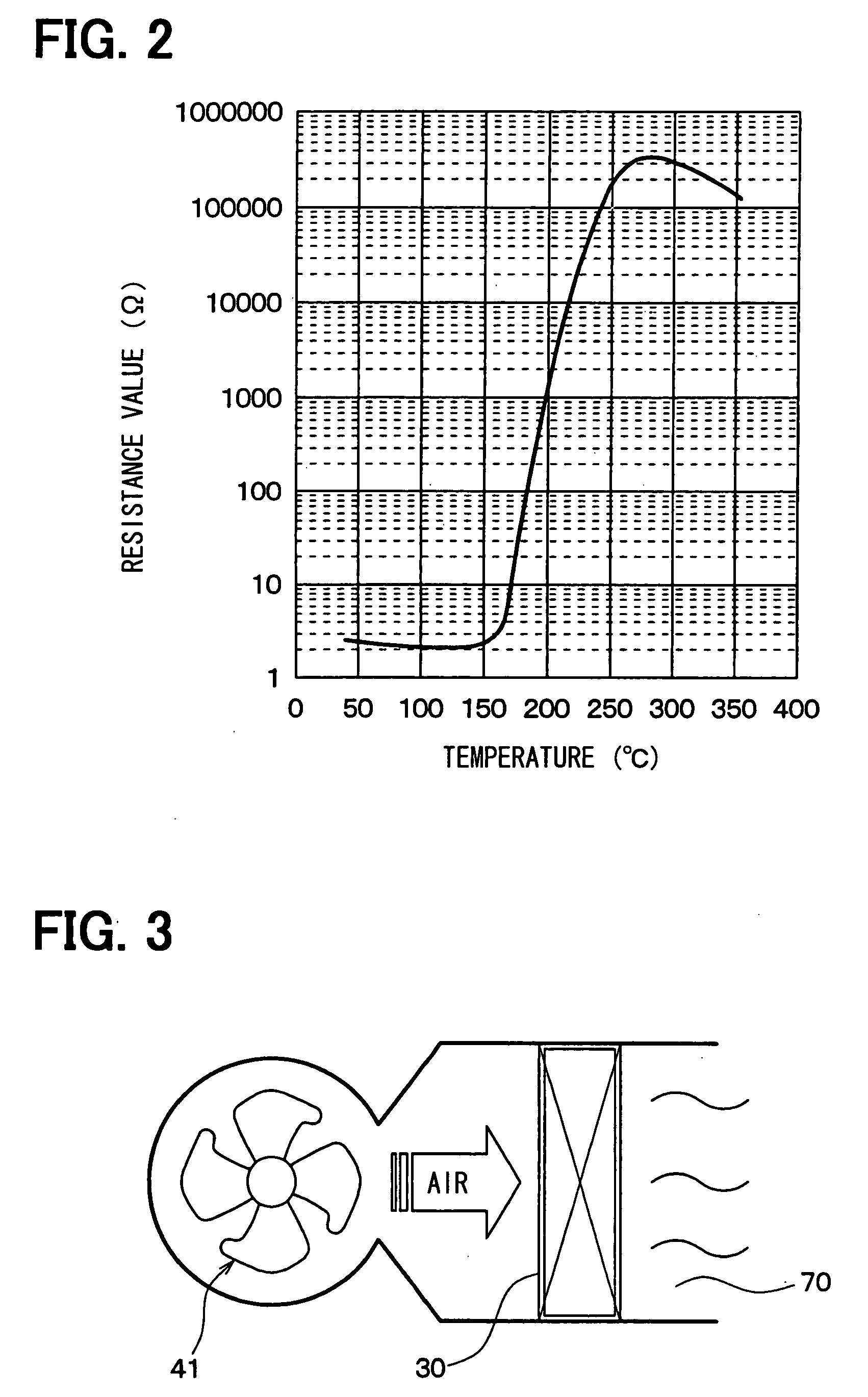
[0057]In this embodiment, different parts from the first embodiment will be mainly described below. In the above-described first embodiment, the volume of air blown against the PTC heater 30 is decreased and the temperature of the PTC heater 30 is increased to increase the resistance value thereof, resulting in decrease in current passing through the PTC heater 30. Together with this, in the first embodiment, the current passing through the drive transistor 13 is also decreased so as to reduce the heat generation of the drive transistor 13, thereby preventing the stopping of the entire system.

[0058]However, when the overheating of the drive transistor 13 is not restrained and the diagnostic signal is subsequently input to the ECU 20 even while the air volume of the blower 41 is decreased, it is preferable to stop the entire system from a viewpoint of protection of the drive transistor 13.

[0059]Accordingly, in the second embodiment, the ECU 20 has a function of stopping the entire sy...

third embodiment

[0069]In this embodiment, only different parts from each of the above-mentioned embodiments will be described below. In the above second embodiment, the entire load drive control system is controlled to stop under a certain condition. When a main heating system, that is, a heater core is provided in the air conditioning unit, the blower motor 40 preferably continues to be driven without stopping the entire system so as not to stop the heating. Reference will now be made to a load drive control system including the heater core in the air conditioning unit.

[0070]As shown in FIG. 6, a load drive control system of the third embodiment is provided with a heater core 80 in the system shown in FIG. 1.

[0071]The heater core 80 serves to heat air passing through the heater core 80 by an engine coolant supplied from an engine 85 shown in FIG. 7. The heater core 80 is disposed between the blower 41 and the PTC heater 30 in an air flow direction as shown in FIG. 7, so as to supply the heated hot...


PUM


Abstract

A load drive controller for controlling a heat generating member by a switching element includes a temperature detection portion for detecting a physical quantity of a level corresponding to a temperature of the switching element, a protection function portion for outputting an abnormality signal corresponding to an overheated state of the switching element when the physical quantity detected by the temperature detection portion is larger than a value, a control portion for causing the heat generating member to generate heat by driving the switching element via a driving portion. Furthermore, the control portion causes a temperature adjustment portion to increase the temperature of the heat generating member when the abnormality signal is input from the protection function portion.

Description

CROSS REFERENCE TO RELATED APPLICATION[0001]This application is based on Japanese Patent Applications No. 2006-179045 filed on Jun. 29, 2006, and No. 2007-15209 filed on Jan. 25, 2007, the contents of which are incorporated herein by reference in its entirety.BACKGROUND OF THE PRESENT INVENTION[0002]1. Field of the present invention[0003]The present invention relates to a load drive controller adapted to prevent a drive transistor for driving a load from overheating, and to a load drive control system having a control means.[0004]2. Description of the Related Art[0005]A control unit having a temperature protection function of preventing a drive transistor for driving a load from overheating has hitherto been proposed in, for example, JP-A-2005-217399. Specifically, a control unit is proposed which includes a circuit substrate with an electric circuit formed thereon, a drive transistor installed on the circuit substrate for driving a load, a cutoff member for electrically connecting ...

Claims


Application Information

Patent Timeline
Patent Type & Authority Applications(United States)
IPC IPC(8): H02H5/04H01H83/00
CPCB60H1/2218H01H37/76B60H2001/2287B60H2001/2231
Inventor WATANABE, HIDEO
Owner DENSO CORP
Why Eureka
Try Eureka