Low-power high-PSRR current-mode microphone pre-amplifier system and method

a microphone and preamplifier technology, applied in the field of cochlear implants, can solve the problems of affecting the performance of the microphone and the preamplifier, limiting the input dynamic range of the hearing instrument to 83 db, etc., and achieve the effect of low power, high dynamic range, and low power

Inactive Publication Date: 2008-01-03
MASSACHUSETTS INST OF TECH
View PDF14 Cites 22 Cited by
  • Summary
  • Abstract
  • Description
  • Claims
  • Application Information

AI Technical Summary

Problems solved by technology

Hearing instruments are typically limited to 83 dB of input dynamic range by available microphone technology.
Such fluctuations, or noise, may significantly detract from the microphone and pre-amplifier performance.

Method used


Image

  • Low-power high-PSRR current-mode microphone pre-amplifier system and method
  • Low-power high-PSRR current-mode microphone pre-amplifier system and method
  • Low-power high-PSRR current-mode microphone pre-amplifier system and method

Examples


Embodiment Construction

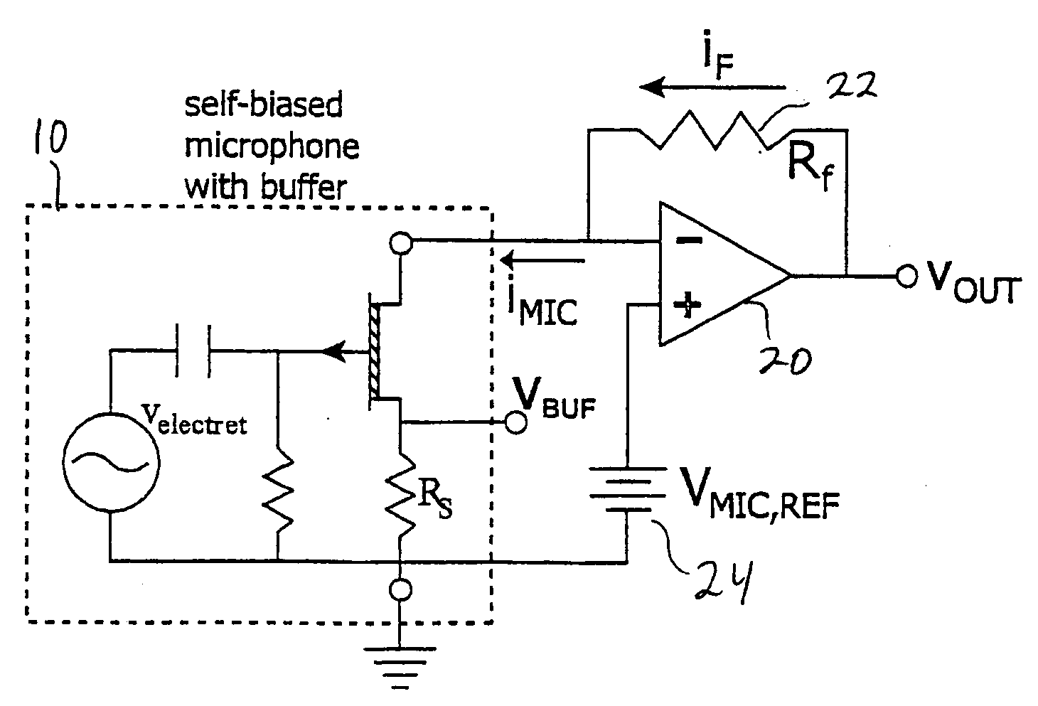
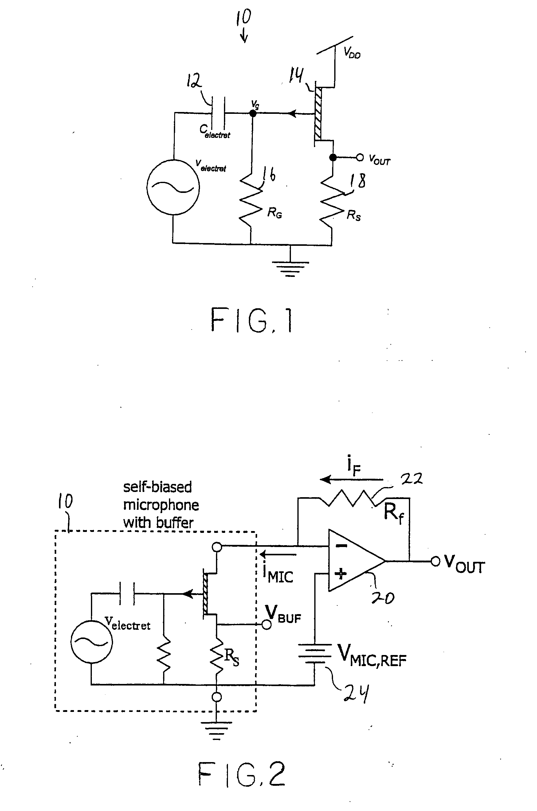
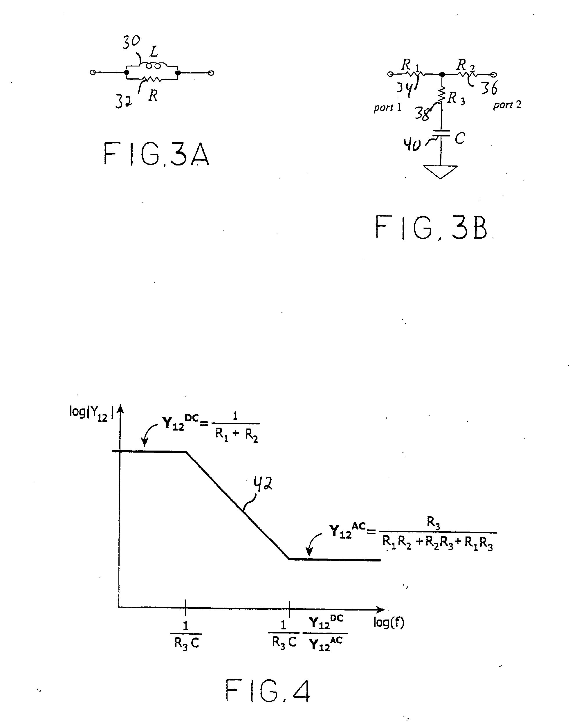
[0029]The invention provides a low voltage microphone system in which a JFET microphone buffer's output current, rather than its output voltage, is transduced via a sense-amplifier topology allowing good in-band power-supply rejection in accordance with an embodiment. The design employs a low-frequency feedback loop to subtract the D.C. bias current of the microphone and prevent it from causing saturation. Wide-band power-supply rejection is achieved by integrating a filter on all current-source biasing. In an embodiment, the design exhibits 80 dB of dynamic range with less than 5 μVrms of input noise while operating from a 2.8V supply. The power consumption is 96 μW which includes 60 uW for the microphone built-in buffer. The in-band power-supply rejection ratio (PSRR) varies from 50 dB to 90 dB while out-of-band supply attenuation is greater than 60 dB until 25 MHz. Fabrication may be achieved in a 1.5 μm CMOS process with gain programmability for both microphone and auxiliary cha...


PUM


Abstract

A low power high dynamic range microphone amplification system is disclosed. The system includes a current sensing amplifier for receiving an input current signal representative of auditory information and for providing an amplifier output signal. The current sensing amplifier includes a DC bias network that includes a cascode filter.

Description

PRIORITY[0001]This application claims priority to U.S. Provisional Application Ser. No. 60 / 488,148 filed Jul. 17, 2003.BACKGROUND OF THE INVENTION[0002]The invention generally relates to hearing aids and particularly relates to cochlear implants. Hearing impairment is believed to affect approximately 10% of individuals in the world. Many such individuals are in need of cochlear implants or hearing aids to listen to normal sounds. Conventional hearing instruments are designed to fit inside the ear, requiring small, low power, wide-dynamic-range front ends with a minimum of external components and good power supply rejection.[0003]The use of wideband clock and telemetry signals in hearing instruments further requires a very high level of superb power-supply rejection in-band as well as at high frequencies. A fully analog hearing instrument should exhibit good power-supply rejection properties in all of its stages prior to rectification. A digital signal processor (DSP)-based hearing i...

Claims


Application Information

Patent Timeline
Patent Type & Authority Applications(United States)
IPC IPC(8): H04R3/00H03F1/22H03F1/30H03F1/34H03F3/185H03F3/45H04R25/00
CPCA61N1/36032H03F1/223H03F1/301H03F1/342H03F3/185H04R2410/00H03F2200/462H03F2203/45138H04R3/00H04R25/00H03F3/45475A61N1/36038
Inventor BAKER, MICHAEL W.O'HALLORAN, MICAHSARPESHKAR, RAHUL
Owner MASSACHUSETTS INST OF TECH
Why Eureka
Try Eureka